With regard to balanced mode radiator (BMR) loudspeakers, “the development time ... is considerably longer than the time required for a conventional cone-based woofer or dome-tweeter.” [1]
This is primarily caused by the long measurement time associated with assessing full vertical and horizontal directivity. One way to speed this up is to use the unified solution offered by the Multi-Scanning Workbench from Klippel. This solution also saves money and space by dispensing with the need for a large baffle and anechoic room. With work from home seemingly here to stay to some extent even after the COVID-19 threat is sufficiently reduced, this becomes even more helpful. A BMR driver is measured with this all-in-one setup to illustrate the capabilities of the Multi-Scanning Work bench and the advantages compared to traditional testing methods.
BMR Overview
A BMR, such as this early Naim prototype supplied by Lampos Ferekidis pictured in Photo 1, uses the same motor and suspension structure as a traditional electro-dynamic speaker but it contains additional “balancing masses” attached to the diaphragm.[1] At low frequencies, a BMR moves like a piston. However, at higher frequencies the typical break-up region is replaced with a bending wave region, like a panel speaker. This leads to less beaming at higher frequencies, giving the BMR a wider dispersion characteristic. Therefore, a BMR behaves more like point source across the full audio band than traditional full-range speakers or two- and three-way designs.
Multi-Domain Measurements
A comprehensive transducer assessment includes many measurements across several domains. It is important to measure different signals in parallel because the effects and the root cause of a specific phenomenon often lie in separate domains. Being able to trace symptoms across domains is necessary for a deep understanding of loudspeaker behavior.
Test Setup
Performing multi-domain measurements places a large set of needs on the measurement equipment and setup used. While there are plenty of high-end consumer and professional audio analysis tools available today, these solutions usually only combine electrical and acoustical testing. When using these options, sound radiation measurements conforming to international standards are typically performed using a baffle in an anechoic room.
However, the accuracy of low-frequency measurements is highly dependent on the sizes of the room, transducer, and baffle and on the effectiveness of the low-frequency absorption. Another problem is baffle vibrations. To combat this, baffles can be made from solid steel or concrete, but the increased weight can lead to handling problems.
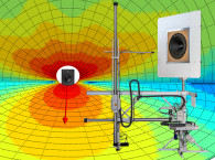
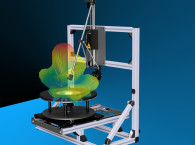
The all-in-one Multi-Scanning Workbench equipped with the Scanning Vibrometer System (SCN) Near Field Add-On, as seen in Photo 2, is a complete but compact solution. This hardware facilitates electrical, acoustical, mechanical, and even magnetic testing (not discussed in this article), and measuring different domains in parallel or switching between these domains is smooth and uncomplicated. The newly released acoustical scanning ability utilizes the same direct sound separation technique used in the Near Field Scanner (NFS), which also supports larger audio devices.[2] This technology has several advantages compared to normal far-field measurements, such as obtaining the full 3D sound radiation data in both the near and far fields in a shorter amount of time than could be accomplished with turntables and minimal microphone arrays.
On top of that, a large baffle and an anechoic room are no longer needed. A small round baffle is sufficient because the signal processing can remove the influence of diffraction at the edges, acoustic shortcut and room reflections. By removing the traditional restricting factors of room and baffle size, this technology can be very accurate at low frequencies even when placed in a normal work or home office. This solution is perfect for comprehensive transducer analysis because it integrates everything that is needed into a space- and cost-efficient unified hardware that can quickly perform multi-domain measurements.
Electrical Measurements
A natural place to start is with the Thiele-Small (T-S) parameters and the impedance curve. There are several different ways to obtain these results, including the delta mass and delta compliance methods that only use electrical signals. However, using a laser displacement sensor in addition is faster, easier, and more precise.[3] Moving on, with electrical sensors and an optional laser, measuring the lumped parameters of a large signal model and nonlinear curves such as force factor, stiffness, and inductance is a straightforward task.[4]
Using the Multi-Scanning Workbench with the laser pointed at the center of the diaphragm, the impedance (Figure 1), T-S parameters, and large signal parameters and curves of the Naim prototype were quickly obtained (Table 1). Figure 2 shows a flat and symmetrical force factor characteristic thanks to the underhung voice coil design.
Acoustical Scanning
Measuring and analyzing sound radiation to extract sound power and directivity with high angular resolution is usually the most time-consuming aspect of the testing process. However, by performing a holographic measurement with direct sound separation using the SCN Near-Field Add-On, a complete scan of the prototype driver up to 20kHz was accomplished in only five minutes (Table 1) with the assumption of rotational symmetry, which greatly reduces the number of measurement points needed for round drivers placed in round baffles. From this scan, the sound pressure output at any point in 3D half space, in either the near or far field, can be generated.
A polar plot of the vertical sound pressure output (Figure 3) and contour plot of the horizontal sound pressure output (Figure 4) were generated in the far field (10m distance). This measurement can be done in any normal semi-reverberant room, and the measurement principle is illustrated in Figure 5, where the room and baffle reflections are removed from the measured response to extract the direct sound. In contrast, similar data (1° angular resolution) using turntables and a single measurement microphone would require up to 32,400 measurement points and take between three and four days, leading to a time reduction factor of ~1,000! Aside from the time savings, this measurement would either need to be done in a large anechoic chamber or outside, which leads to other issues such as wind, ambient noise, or temperature variations that can corrupt the data.
Single-Point Measurements
For some acoustical measurements such as equivalent input distortion or impulsive distortion, also known as Rub & Buzz, it is always recommended to place the microphone in the near field in order to maximize SNR and sufficiently reduce any room influence.[5],[6] For others such as on-axis response and total harmonic distortion (THD), they are usually done at the standard distance of 1m or farther to ensure the measurement is in the far field.
However, after performing an acoustical scan, a (room) correction curve can be generated that compensates for the position of the measurement microphone and any unwanted effects of baffles or non-anechoic rooms. Therefore, the microphone can be positioned in the near field to maximize SNR, while measuring in a reverberant room and the virtual evaluation point is at another distance such as in the far field. This means that standard measurements at an evaluation point much farther away, even farther than the physical dimensions of the room, can be done in a normal work or home office while keeping a single microphone in a fixed position. For example, Figure 6 shows the transformed on-axis response and harmonic distortions at 1m distance, even though the microphone was placed at 10cm distance.
Mechanical Scanning
When developing a BMR, scanning the diaphragm with a laser displacement sensor to assess the transducer’s modal vibration is essential. At lower frequencies, the scan is less interesting because the driver is acting as a rigid piston. Figure 7 shows that even at 1kHz, the Naim prototype is still moving entirely in phase. At higher frequencies, traditional mid-range and full-range drivers enter the break-up region, which can lead to large peaks and dips in the frequency response that can negatively influence the audio quality.
In order to compensate for these effects and flatten the frequency response, BMRs use balancing masses added both inside and outside the voice coil.[1] The modal vibration data, obtained in just 8 minutes (Table 1), is useful for knowing where to place or adjust the balancing masses and verifying that their location, based on previous calculations or simulations, is correct.
Conclusion
BMR loudspeakers perfectly illustrate the advantages of the Multi-Scanning Workbench because of the need for comprehensive acoustical information including high-resolution vertical and horizontal directivity as well as analysis of the modal vibrations in addition to the standard electrical and single-point measurements. Due to the operation across four domains (acoustical, mechanical, electrical and magnetic)as well as the unique advantages of the holographic scanning with direct sound separation, the testing times in Table 1 add up to only 24 minutes. Additionally, the total cost and space of measurement equipment can be greatly reduced compared to other solutions that combine different tools for each domain and use anechoic chambers and large baffles. The Multi-Scanning Workbench is ideal for anyone wanting to completely analyze transducers, even in a non-anechoic environment such as a work or home office. VC
References
[1] E. L. Ferekidis and K. Fink, “The Naim Balanced Mode Radiator”, (2009).
[2] C. Bellman and W. Klippel, “Holographic Nearfield Measurement of Loudspeaker Directivity”, Audio Engineering Society Convention Paper 9598, September 2016.
[3] W. Klippel and U. Seidel, “Fast and Accurate Measurement of Linear Transducer Parameters,” Journal of Audio Engineering
Society, Paper 5308, May 2001.
[4] W. Klippel, “Measurement of Large-Signal Parameters of Electrodynamic Transducer,” Journal of Audio Engineering Society, Paper 5008, September 1999 September.
[5] IEC 60268-21 Sound System Equipment—Part 21: Acoustical (Output Based) Measurements, International Electrotechnical Commission (IEC) 2018.
[6] W. Klippel, “Measurement and Application of Equivalent Input Distortion,” Journal of Audio Engineering Society, Volume 52, Issue 9, pp. 931-947, September 2004 September.
Resources
In-Situ Compensation (ISC), Klippel,
www.klippel.de/products/rd-system/modules/isc-in-situ-compensation.html
Near-Field Scanner System (NFS), Klippel,
www.klippel.de/products/rd-system/modules/nfs-near-field-scanner.html
Scanning Vibrometer System (SCN), Klippel,
www.klippel.de/products/rd-system/modules/scn-scanning-vibrometer-system.html
SCN Near-Field Add-On (SCN-NF), Klippel
www.klippel.de/products/rd-system/modules/scn-nf-scn-near-field-add-on.html
 About the Author
Andrew Taylor received his bachelor’s degree in electrical engineering at the University of Kansas in Lawrence, KS in 2015. As he finished his master’s in electrical engineering with a concentration in musical acoustics and signal processing at the University of Rochester in Rochester, NY, he interned at Klippel in 2016. He has been a fulltime employee at Klippel since 2017, where he now splits time between audio analyzer hardware development and technical writing and content creation.