By Christian Bellmann and Ruben Hauschild (Klippel GmbH), and Mattia Cobianchi (Bowers & Wilkins)

Where should I place my speakers? In theory, I think I know the answer, but in reality, finding a good compromise between the optimal listening setup and the arrangement of the interior in a living room might become a controversial issue. With this issue in mind, in-wall loudspeakers are a very clever idea. The loudspeakers are integrated in the walls or the ceiling to be almost invisible. This can provide an optimal listening experience and doesn’t interfere with the interior design.
Over the years, the applications, capabilities, and sound quality of in-wall loudspeakers have increased. Starting from single broadband transducers, often with medium audio quality, similar to those found in public places (supermarkets) or public transport (planes or subways), high-quality, multiway in-wall loudspeakers are serious alternatives to ordinary loudspeaker systems nowadays.
Also, in professional applications (cinemas or theaters) in-wall setups become more and more important and are scaled up to planar arrays with hundreds of distributed transducers used for modern 3D sound reproduction and virtual reality using ambisonics and object-based algorithms.
These applications are defining new requirements for the measurement process as well. The directional characteristics are an especially important factor, because the direction in which a loudspeaker emits sound highly affects the interaction with the listening room and the listening experience. Audio system developers need that 3D information, accurate in both magnitude and phase, to verify their designs and tune their DSPs. Moreover, the growing technical interest and knowledge in the hi-fi community is pushing the demand for accurate 3D data. Nowadays, new freeware simulation and auralization tools give almost everybody the opportunity to do simple acoustical simulations.
Measurement Challenges
However, the directivity measurement is still a challenge. Traditionally, these measurements have to be performed under free- and far-field conditions, which can be realized over a wide frequency range in an anechoic chamber. But for low frequencies (f<100Hz), most test rooms are insufficiently damped, which causes systematic measurement errors. Also, the large distance between loudspeaker and microphone (r>4m) makes an accurate phase measurement at high frequencies (f>10kHz) almost impossible, because small deviations in temperature affects the speed of sound and the propagation delay as well.
Coping with these limitations, the response of the device under test (DUT) is directly captured by moving the microphone at multiple positions in the sound field, typically placed on a sphere. Practically, this can be realized using either a microphone array or turntables.
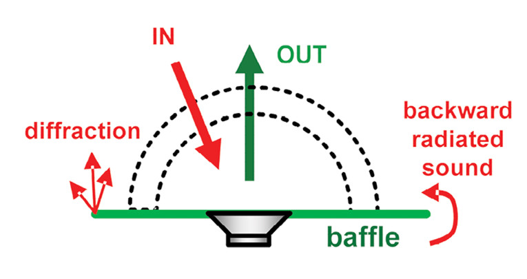
In-wall speakers need to be measured in half space (2π) by mounting the DUT either on the ground floor of a semi-anechoic chamber or using a free-standing baffle in a full anechoic room. Unfortunately, a baffle of limited size may produce new measurement errors caused by diffractions at the baffle’s edge and interference with the backward radiated sound. Using a rectangular baffle, as recommended by the International Electrotechnical Commission (IEC), can reduce but not avoid these artefacts.
Holographic Directivity Testing
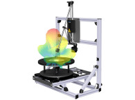
Due to these known issues, Klippel has established a new approach for directivity testing that overcomes these problems. The system is designed to measure loudspeaker systems in almost any acoustical environment (e.g., offices) with the Near Field Scanner System (NFS).
A robotic arm positions the microphone along two nested layers in the near field of the loudspeaker being tested. The DUT remains at a fixed position in the center of the scanner. This simplifies the handling for heavy devices and ensures a constant room excitation and reflections during the scanning process.
Based on this near-field measurement, the sound field radiated from the loudspeaker is identified using solutions of the wave equation (Spherical Harmonics, Hankel functions).
Due to the scanning along a double layer, the Direct Sound Separation (Klippel’s patented technology) uses the additional phase information to detect the direction of the sound wave and can remove all room reflections from the direct sound of the loudspeaker.
This provides a new level of measurement accuracy, including a complete and comprehensive description of the entire sound field (near and far field). Moreover, it provides precise phase data also at high frequencies (f>10kHz) and a maximum robustness against external influences (e.g., reflections).
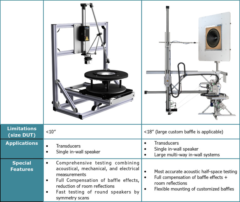
The holographic measurement approach is also adaptable to half space testing (2π). Half-space data can be acquired with different scanning solutions (Table 1). For small speakers, the multi-scanning workbench can be used and the acoustical measurement can be combined easily with electrical and mechanical measurements. Larger devices can be measured with the Near Field Scanner Carousel using an added baffle. Custom-made baffles are also supported.
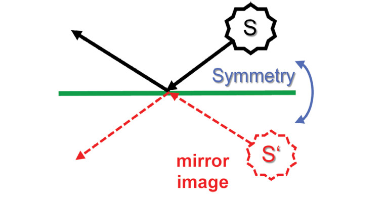
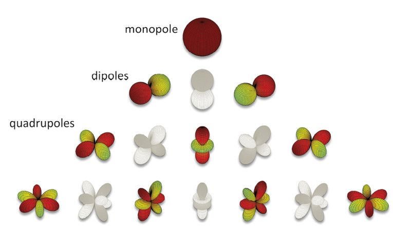
We know from basic physics that a reflection on a plane can be modeled by a mirror image of the sound source (Figure 1). This virtual symmetrical sound field then can be modelled by using only a subset of spherical harmonics that matches this symmetry condition (Figure 2).
Finally, the holographic wave expansion can be applied. Furthermore, the Direct Sound Separation is opening new possibilities (Figure 3). The measurement artefacts caused by the baffle (diffraction and backward radiated sound) can be identified and eliminated from the direct sound of the loudspeaker, because they are outside the scanning surface. This produces perfect half-space data as if measured in an infinite baffle.
Measurement Example
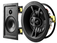
To illustrate the performance of this testing method, measurements were carried out on the Bowers & Wilkins CWM 8.5D (Figure 4). The CWM 8.5D is a high-performance compact in-wall loudspeaker that takes advantage of the technologies of the B&W flagship 800D3 series. It employs a 7” bass-mid cone transducer and a 1” diamond dome tweeter.
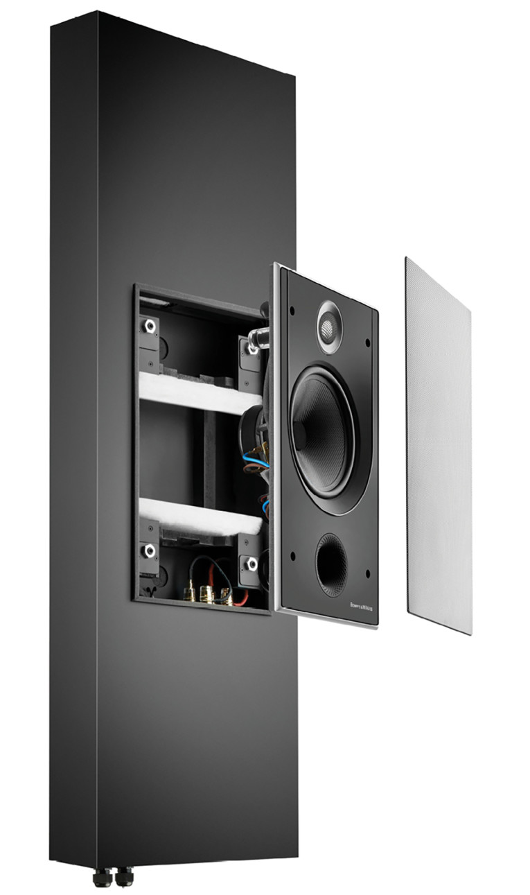
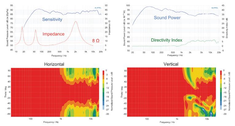
The 7” bass-mid cone breaks up in a controlled and progressive fashion from a relatively low frequency because of the cone’s use of the proprietary Continuum technology. The speaker therefore maintains the ratio between the effective radiating area and the reproduced wavelength nearly constant across the passband. This results in an almost constant and very smooth horizontal directivity from 1.5kHz to 15kHz. This dynamic is visible in the -6dB iso-contour shown in Figure 5.
The damping component’s careful optimization in Continuum’s composite structure and the anti-resonance foam plug used in place of the dust cap also assures that the nonlinear distortion associated with break-up modes is very low. The CWM 8.5D’s tweeter has a very low-resonance frequency. It is crossed over at around 3.5kHz, so the bass-mid reproduces most of the loudspeaker’s critical midrange and blends seamlessly with the tweeter directivity. The low-resonance frequency of the tweeter also allows for an ultra-low distortion in the tweeter passband while the CWM 8.5’s diamond dome guarantees that the first axisymmetric high Q break-up mode falls almost two octaves above the audible range at about 72kHz.
Measurement Setup
Due to the design, the CWM 8.5D needs a specific mounting. That’s why a customized baffle was used to mount the speaker on the NFS Carousel. The scan was performed in a normal office room with about 1,000 measurement points and took about two hours. The spherical wave expansion was calculated with expansion order N=25, which was sufficient to characterize the entire sound field over the full audio band (20Hz to 20kHz). The accuracy is automatically self-checked during the identification using the redundant information of the raw measurement data.
Results
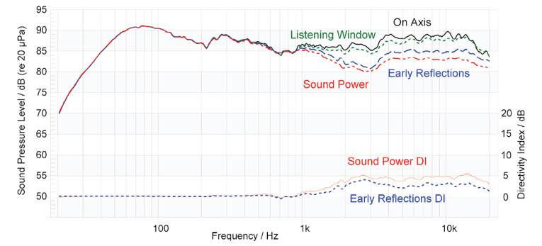
Finally, the CWM 8.5D’s directivity can be analyzed by checking traditional far-field measurements (frequency response, sound power, and directivity index) or by simplified characteristics, such as the CTA2034 Spinorama. In addition, new near-field characteristics, such as the SPL distribution in a specified listening zone, can be analyzed.
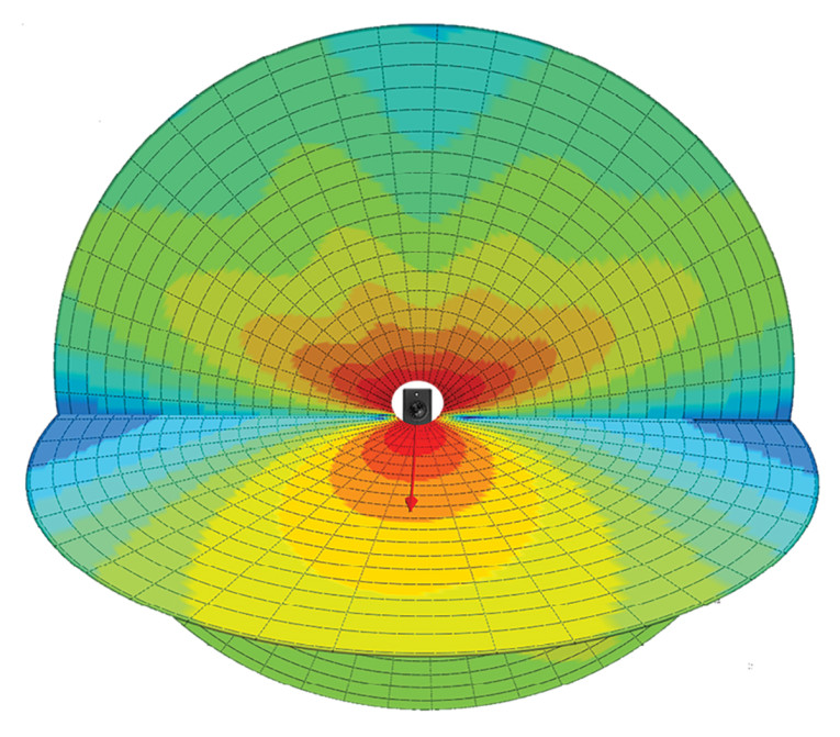
The results show a very consistent horizontal coverage of ±50° with an almost constant directivity index of 6dB above 1.5kHz. The CTA2034 Spinorama given in Figure 6 shows a deviation of about ±3dB for the on-axis frequency response and is even smoother within the listening window. The comprehensive holographic parameter includes the energy transfer from near into far field as well. Thus, the precise sound pressure field can be calculated at any distance including the very near field of the device. In Figure 7, the sound pressure distribution of the CWD 8.5D at 2kHz is visualized. This accurate 3D data can be used for acoustic simulation software that predicts the performance of the loudspeaker in a listening room or any other application (public transport, alarm systems in buildings, etc.).
Conclusion and Summary
The holographic measurement approach provides comprehensive, easy-to-interpret data that is relevant for transducer engineers as well as audio system designers. Hi-fi enthusiasts may also be interested in this information and motivated to learn about good sound quality and are willing to pay for it when evidence is provided.
Thus, objective testing is an important criterion besides the perceptual evaluation. In addition, the measurement produces the data that is required for room simulation tools, such as EASE, to simulate different test scenarios, including different loudspeakers placements, within an acoustically simulated space. It is well suited for professional or consumer applications. aX
This article was originally published in audioXpress, December 2021.
About the Authors
 Christian Bellmann studied mechatronics at Dresden University of Technology with a focus on control engineering, power electronics, and electrical drives. In 2013 he received a Diploma degree for his thesis “Separation of direct sound and room reflections using holographic methods,” which was supervised by Dresden Technical University and Klippel GmbH in Dresden. After graduation, he joined Klippel, where he is currently engaged in the research and development of loudspeaker measurement systems with a focus on acoustical holography.
 Rueben Hauschild studied electronic engineering at Dresden University of Technology with a focus on communication technology and acoustics. In 2019, he received a Diploma degree for his thesis “Maximizing the efficiency of active speaker systems with non-linear control,” which was supervised by Dresden Technical University and Klippel GmbH. After graduation, he joined Klippel, where he is currently engaged in the support, research, and development of loudspeaker measurement systems with a focus on loudspeaker simulation.
 Mattia Cobianchi is a transducer and acoustic engineer, specializing in drive units and cabinets modeling, innovative measurement techniques for loudspeakers characterization and psychoacoustics. He has a MSc in Electronic Engineering and a Diploma in Acoustics. He’s currently Senior Transducer Engineer for Bowers & Wilkins and a PhD student in the Music Department of Goldsmiths University of London.