And that was before I tried multichannel surround. With a good recording, this transparent naturalness extends to an enveloping soundfield that at its best can make you think you’ve been listening from just outside the concert hall doorway, and now you’ve walked inside!
I haven’t yet heard DVD-A, which has also received rave reviews, but SACD seems to be winning. The Acoustic Sounds catalog and The Absolute Sound music reviews have more SACDs than DVD-As, and the margin appears to be increasing.
Project Choices
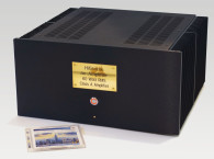
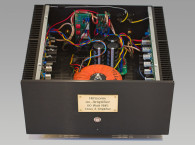
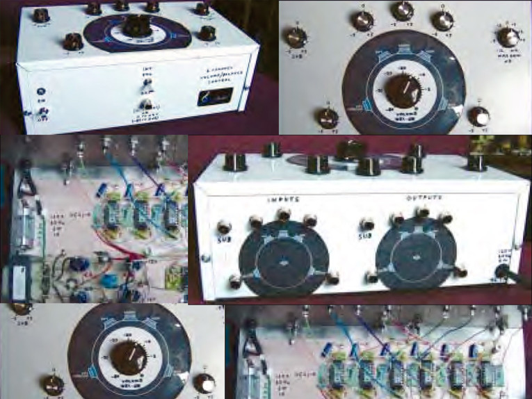
My SACD player and many other multichannel sources don’t have a master volume control. So I designed and built the unit described here (Photo 1).
I decided against the following alternatives:
1. Six-gang step attenuator plus six balance pots. The latter would require signal reduction at mid-setting; also, I wanted remote controllability, which would require seven motorized attenuators
very expensive.
2. The Analog Devices SSM2160 Serial Input Balance/Master Volume 6-channel control. While this uses the same ultra-high quality analog VCAs (Voltage Controlled Amplifier/Attenuator) as in the devices I used, I wanted analog, not digital, control. I didn’t mind needing six (inexpensive) ICs instead of one.
3. Digital processors what? Degrade my SACDs to “CD quality”? No thanks!
Instead, I used the Analog Devices SSM2018T analog VCA. This $8 IC has 140dB gain control range, THD of ≈ 0.01% biased in Class AB (I use Class A), noise of about 97dB below 0dBu (0.775V RMS), and a very linear dB attenuation versus control voltage law. Also, the VCA needs no trimming repeatability from unit to unit appears to be within about 0.2dB.


Functional Description
1. Volume The control is calibrated from 0dB (maximum volume) to −80dB; a switch allows use of an external 10kΩ linear pot (“wired remote”) or a 0 to +4V control signal (0V →−80dB; +4V →0dB).
2. Balance Six individual channel pots provide ±5dB range (you can easily change the range if desired).
3. Maximum gain This pot sets the “0dB volume” gain of the unit within a range of ±12dB (also changeable).
Note: The speaker diagram shown on the controller top in Photos 1 and 2 is the I.T.U. standard multichannel layout, recommended for music. Notable differences from the THX movie standard are:
1. Five full-range speakers are recommended (but not required).
2. Front left/right units are ±30° in relation to center.
3. Rear surrounds are 110° from front center.
4. Dipole surrounds are not recommended.
5. All five speakers are equidistant from the listener.
6. No electrical delay is added to surround speakers. With most orchestral surround SACDs, the rear surround mikes receive hall ambience from the rear, therefore already appropriately (naturally) delayed.
I must comment most emphatically that with such a recording, I find the sound to be absolutely ethereal in its naturalness. Once heard, there’s no going back!
voltage input max gain and balance pots
set to 0db.
I used a Bud box, CU-2110B (10″ × 6″ × 3.5″), Newark 91F697. Being in a hurry, I didn’t bother with a PC board. I simply glued and soldered parts and wires all over the solid copper surface of a piece of unetched board material (Photo 1). Looks crude, but can’t be beat for solid grounding!
(My “day job” is designing microwave oscillators; I’ve built protos with this “air-bridge over ground plane” method that work over 10GHz, often better than the PC board production units.)
Circuit
The audio path is simple: VCA 1 (shown in Fig. 1A; six units total) is fed audio through RA (1−6) to pins 4 and 6. Audio output is from pin 14, which also feeds pin 3 through RB (and HF bypass CB). With zero voltage at the gain control pin 11, audio gain is the ratio of RB to RA, here set to unity. (Refer to the Analog Devices SSM2018T data sheet, for description and specs. See References)
Audio frequency response is DC to 200kHz, the latter being the −3dB HF rolloff point. CA is the recommended HF compensation cap. RD supplies 0.51mA to pin 12, which biases the VCA in pure Class A mode. Pin 11, the gain control point, has a slope at +25°C ambient of −30mV/dB, with unity gain (0dB overall) at 0V applied.
This -30mV/dB slope is proportional to absolute temperature (°K); at +25°C this represents a gain-in-dB tempco of −3300ppm °C1. Uncompensated, a 15°C ambient rise (27°F, say from 70°F to 97°F) would change the “gain,” if set to −40dB, to a value of −38dB (0dB gain setting is temp-independent). While a 2dB volume increase with regard to −40dB if you’re listening at 97°F is not serious, I decided to provide temp-compensated control-drive signals (which I describe later).
Also, even at this peak level, controller distortion is below 0.01%, and mostly second and third harmonics (like a tube amp, but much lower in level). After extensive listening with and without the controller, I didn’t notice any sonic degradation or audible noise.
Power Supply
The supply (Fig. 1B) is completely straightforward and simple: regulated ±12V supplying about 80mA each. With the four 1000μF filter caps, hum and noise are completely negligible. A note on the power transformer (T1): This is a high-isolation split bobbin type from SPC Technologies. High-isolation indeed. I measured primary/secondary capacitance of only 16pF at 60Hz, this is an impedance of 166MΩ. This controller will not introduce any audible hum into your system.
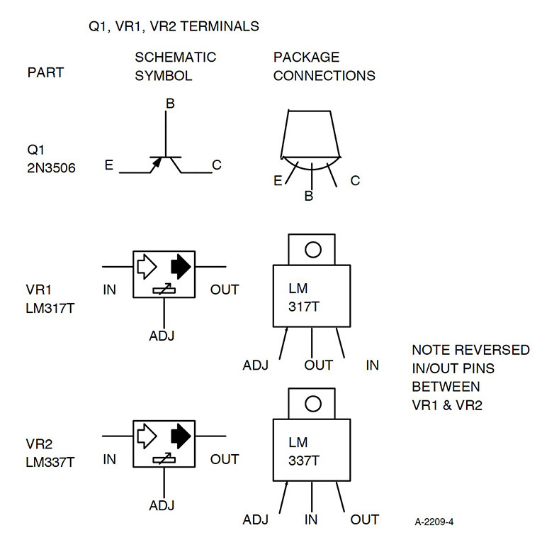
The VCA chip is rated for ±18V maximum supply at up to +85°C (185°F). With ±12V supply at normal temperatures even for the Sahara the circuitry should last 10,000 years (barring corrosion, of course). Regarding the supply voltages (trimmed by TP1 and TP2), they should be set to within 10mV of ±12V. The regulators (VR1, VR2) became rather warm without heatsinks, although not excessively. I used heatsinks to be conservative.
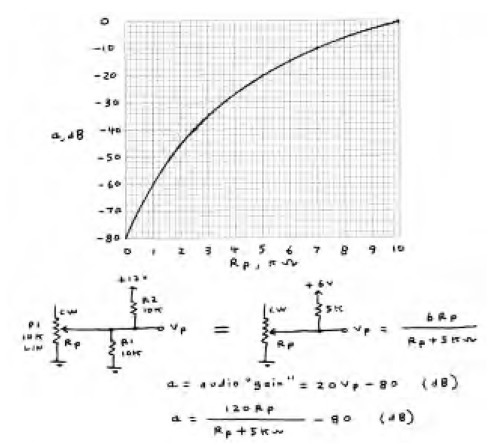
Master volume is controlled by either (a) P1, a 10kΩ linear pot; (b) an external 10k pot, switched in by S2, to serve as a “wired remote”; or (c) an external DC voltage of 0 (for −80dB) to +4V (for 0dB). Since the VCA control function is linear voltage-to-linear dB, a linear pot (unloaded) would provide an 80dB attenuation range with linear dB versus control rotation. However, this would not provide fine enough resolution at normal volume settings. So I selected R1 and R2, providing a 5kΩ load to the 10k pot, to taper the dB versus rotation function(2). As such, mid rotation produces 20dB attenuation, similar to a typical audio taper (≈ log) volume control pot. See Fig. 2.
As you can see in Photo 1, the tapering allows <1dB resolution from 0 to −10dB, smoothly steepening to allow an 80dB range. In operation, the volume control characteristic feels natural and precise. The output of A1-a (after D1) is biased and scaled to produce −6V at minimum volume and 0V at maximum volume.
When using a “wired remote” pot, switched by S2, there was concern that an open pot, cable, or connection would result in a default to maximum volume: the pot wiper voltage fed to A1-a pin 3 is normally 0V (for −80dB) to 44V (0dB). But an open pot would increase this to +6V, resulting in +40dB gain and toasted tweeters (at least!). Diode D1 limits the output fed to R5, limiting pot default volume to about +1dB (above maximum).
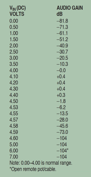
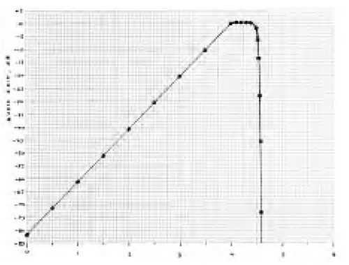
But at Ed Dell’s suggestion, I added a circuit to default volume to maximum attenuation (Q1, R15, R16, R17). A voltage greater than 4.60V at A1-a pin 3 immediately shuts down the audio gain to about −104dB, as shown in Fig. 3 and Table 1. Switch S2 greatly increases the Spousal Acceptance Factor for example, wife can instantly flip switch and mute excessive volume set by audio hubby on his concealable remote volume box!
A1-b is an inverting summing “amplifier” (“gain” from A1-a = 0.412 at +25°C). With P2 (“maximum gain” pot) centered, and P1 (volume) at maximum CW (clockwise) rotation, the 0V fed to R5 results in 0V also at A1-b output (pin 7). This (with balance pot PB centered; only one of six shown) feeds the VCA control pin 11, a 0V signal, which results in an audio gain of 0dB.
RT1 is a linear +3500ppm/°C compensation resistor that causes non-zero (attenuation control) voltages out of A1-b (pin 7) to have this temperature coefficient, which is the same that the VCAs need for essentially zero drift. Analog Devices suggests the model PT 146 (1.00k ±1% @ +25°C) from Precision Resistor Co., Largo, Fla. The area code on the AD data sheet has been changed; the correct phone number is (727) 541-5771, ask for Arlene.
The output of A1-b feeds six resistors (RE1−6), one for each channel, to the corresponding VCA (1−6) in Fig. 1B. These resistors, together with RF (1−6) from the balance pots PB (1−6), supply the control voltages to the VCAs. The balance pots are supplied ±6V (@ +25°C), proportional to absolute temperature courtesy of RT2 and A2 (a, b), Fig. 1A.
Note: The circuitry could have been simplified by first combining the volume and balance signals, then temperature compensating with one TC resistor.
However, Precision Resistor Co. usually stocks only the 1.00kΩ value, and this would have required more drive current to the VCA control inputs, using the PT 146 as a shunt element. In addition, a series/shunt resistive compensator would lower the effective tempco. RF (1−6) sets the balance controls’ range (±5dB with 196kΩ). Should you desire more range (up to about ±20dB), select the closest 1% standard value to 973kΩ/B, where ±B is the desired balance range in dB.
Calculating Values
Calibrating dB attenuation versus volume control position is simple due to the precise and linear 20dB/V relation regarding pot P1 voltage fed to A1-a pin 3. If a = “gain” in dB (negative here), and VP is the pot output voltage, then a = 20 VP − 80, and VP = (a + 80)/20. So with a voltmeter measuring VP, you can make panel markings corresponding to any desired dB values. After I did this, I checked attenuation values with sine wave levels down to 80dB attenuation. Results agreed well within the thickness of my panel marking lines (all six channels).
Regarding the balance and maximum gain controls, these pots are essentially unloaded (as opposed to the volume control). Therefore, if desired, you can make panel markings (as I did) by measuring either wiper-to-end resistance (before connecting pots) or wiper voltage in-circuit; dB values are very nearly linearly proportional to both, with 0dB at mid-rotation (0V at wiper).
I recommend these calibrated panel markings; multichannel recordings differ “markedly” (sorry about that) in their optimum front/rear gain settings, also considering individual listening preferences. Panel notations allow you to record optimum balance (and overall level) settings for any given disc.
Construction Recommendations
1. Do not use a 3-wire power cord to AC ground the chassis, unless none of your audio equipment is so grounded; ground-loop hum may result. For safety, you can ground one piece of equipment (probably the power amp if a multi-channel unit is used).
2. If you use a solid copper ground plane board (as I did), you can mount insulated parts (IC sockets, regulators, filter caps) on a piece of wood glued to the copper plane. I used balsa wood, sticking such leads into it (carefully avoiding depth that could short to ground), then securing with a drop of Krazy Glue adhesive.
3. You could use solderless breadboards (“proto boards”). I’ve used them to 100MHz. The maximum audio gain here is only +17dB. Capacitance between adjacent proto-board strips is only about 3pF. However, I would dedicate one board to the VCAs, spreading them across the board, and bypass each VCA supply voltage with a 10μF, 16V cap to ground.
4. For audio jack in/out wiring, I simply used unshielded wire point-to-point. Interwiring capacitance is only 0.3pF (26MΩ @ 20kHz; with 1kΩ audio sources, 20kHz crosstalk is only −88dB).
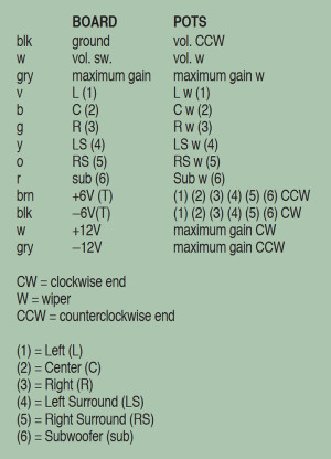
5. I used rainbow-ribbon cable to connect the eight pots. Table 2 shows the legend I used. Because all six balance pots have common end connection, only 13 wires were needed. Of course, since all pots carry only DC control voltages, crosstalk with these wires is not an issue.
Usage
This mulitchannel volume/balance controller is an inexpensive device allowing an SACD or DVD-A source to drive up to six power amplifiers, while maintaining the outstanding transparency and resolution of this source material. While lacking bass management, even the inexpensive SACD players have this, as well as many subwoofers.
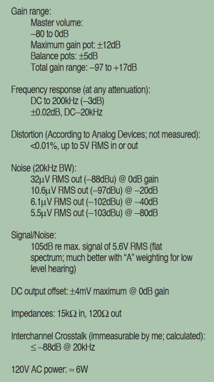
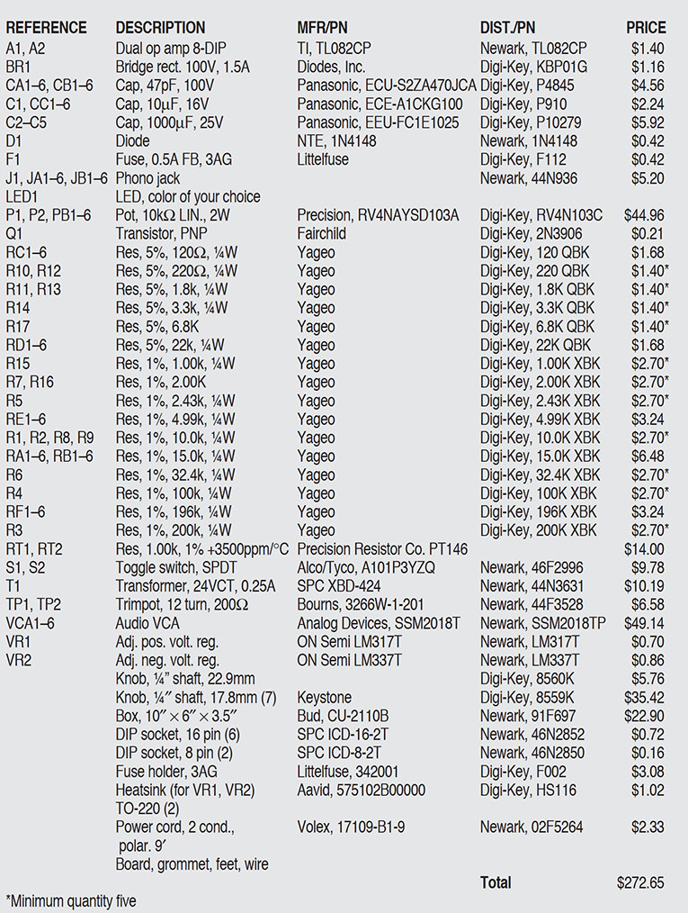
Operating in pure Class A analog mode, with the simplest possible audio path, this versatile and voltage-controllable unit will allow you to enjoy the dramatically realistic surround capabilities of these relatively new formats, with up to six channels of basic power amp/speaker combinations. Table 3 shows the performance summary; Table 4 is the parts list.
References
1. Analog Devices says -3500ppm/°C. This is close enough.
2. For best accuracy, you should select R1 and R2 to equal half the resistance of pot P1, within 1%.
www.analog.com/media/en/technical-documentation/data-sheets/SSM2018.pdf
www.analog.com/media/en/technical-documentation/data-sheets/SSM2160.pdf
This article was originally published in audioXpress, February 2003.


