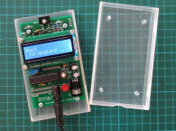

Here is a simple portable device that can help answer the question about peak voltage and peak current requirements and whether or not your power amplifier is capable of driving your loudspeaker without clipping.
Before I began designing this device, I decided several key objectives. I wanted this device to include all the necessary connectors and cabling so that its connection between the power amplifier and the loudspeaker would be easy. It should also be able to simultaneously measure the peak value of the voltage and the peak value of the current with a flat frequency response across the audio spectrum.
And, I wanted it to be able to measure the peak value of a half-cycle period of a 10-kHz sinus signal and have a long storage time for the peak value to enable easy reading of the values with an external DC voltmeter.
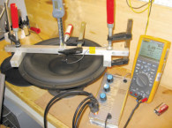
For the device’s power supply, I chose a 9-V battery to increase its flexibility since it is not always easy to found a line voltage supply. Also, the battery eliminates possible problems due to grounding or to floating power amplifiers outputs (with no reference to the ground). The Photo above shows the completed detector.
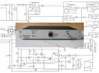
Click here to read the full article in PDF
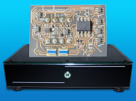
 The author has a small quantity of PCBs (manufactured as shown in the article) for the construction of this device. If you are interested, send George an e-mail here.
This article was originally published in audioXpress March 2015 — Focus on Test & Measurement Edition
AUDIOXPRESS UPDATE
The author suggested a modification to the original article.
The Diode D4 is removed from the circuit of the Peak Detector. A new diode D5 (type 1N5819) is inserted between the Battery (+) pole and the 9V pin of the circuit. This will offer a better protection in case of accidental reverse polarity.
There’s an additional file indicating this modification for download here.