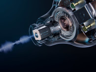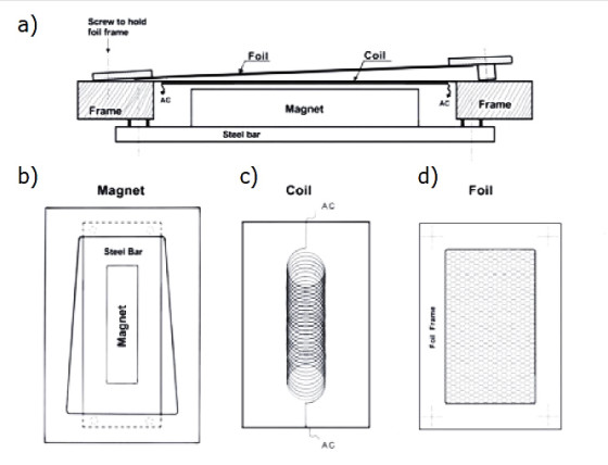
the magnet and steel bar (b), the diaphragm with a flat coil (c), and an aluminum foil membrane
on the frame (d).
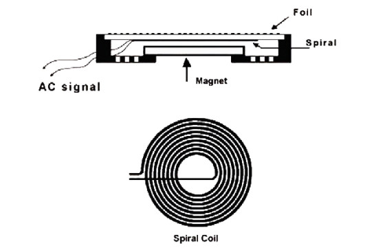
The flat coil is glued to the diaphragm. The diaphragm is near to and facing the magnet’s north or south side. The membrane, which is very thin, is made of a nonmagnetic but electrically conductive material (e.g., aluminum foil). This foil membrane is independently mounted close to and in front of the coil/diaphragm’s surface.
An AC signal in the coil generates a varying magnetic field that interacts with the permanent magnet’s field and results in coil/diaphragm movement. The varying magnetic field from the coil generates a current in the foil membrane, which again generates a magnetic field that interacts with the existing magnetic field and causes the foil membrane to move.
The two independently moving surfaces each generate sound. The coil/diaphragm sound pressure level (SPL) falls with increasing frequency. The foil membrane efficiency can be adjusted so the SPL grows with increasing frequency, and it can be exactly the reverse of the coil/diaphragm. This new driver technology configuration results in an unusually flat SPL/frequency response with exceptionally low narrow-band intensity variation (i.e., peaks and dips) in the SPL response and very low distortion at any “active” frequency. In fact, the driver’s measured performance exceeds that of any known tweeter.
The transducer is also unique among electromagnetic transducers in that the force acting on the membrane is uniformly distributed over much of it, as in an electrostatic sound transducer, but with substantially more power per square unit. As a narrow-band transducer, the driver can become exceedingly efficient.
Figure 1 shows a simplified driver concept as one way of executing the technology. The design has been used as the basis for several working tweeter-driver prototypes.
The Foil Membrane’s Functionality
The prototype tweeter driver has a flat stretched coil. The coil is pressed and glued together. Then, it is pressed and glued to the diaphragm. The coil then assumes a flat, rigid form that will not bend or twist. The coil’s mass on the diaphragm is relatively high in this model.
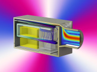
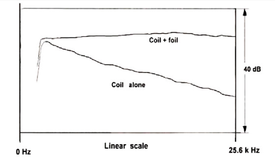
Figure 2 provides two SPL vs Frequency plots (note a 1/5 octave smoothing has been applied to these curves). One plot shows a working prototype tweeter driver with two moving surfaces (i.e., both the coil/diaphragm and the foil membrane).
The other plot shows a working prototype tweeter driver with only the coil/diaphragm. The foil membrane is omitted. The SPL increases from approximately 30 dB for the single-surface prototype to approximately 32 dB for the dual-surface prototype at 2 kHz. At relatively low frequencies (2 kHz), the output (sound) is generated by the diaphragm and the foil membrane. But at 20 kHz, the SPL increases from about 16 dB for the single-surface prototype to about 32 dB by adding the foil membrane. For everything other than the lowest frequencies handled by the driver, the foil membrane is the most significant of the two sound-generating surfaces.

Prototype Driver Data
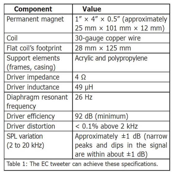
A prototype driver has been used as a tweeter in a speaker system. Table 1 displays the EC tweeter’s specifications and measured performance.
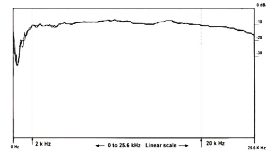
Figure 3 shows the response from a white-noise signal to the driver filtered with a 1-kHz, 24-dB/octave high-pass filter. Two lines are shown in the plot: one is with maximum resolution and the other is filtered. The difference is most noticeable below 4 kHz. The frequency scale (0 to 25.6 kHz) is linear.
Alternate Driver Configuration
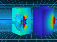
Figure 4 is a simplified drawing that shows a different way to make the driver. The driver uses the new concept as described. Here the coil is a flat spiral shape that is placed over a round permanent magnet.
Modified Dynamic Driver
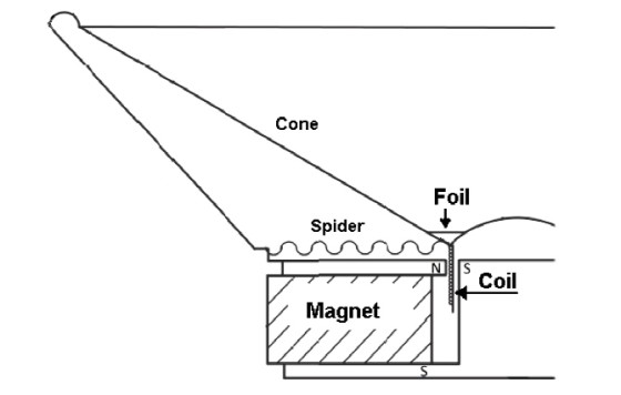
Figure 5 shows half of a modified dynamic driver that has all the elements of a conventional dynamic driver, but includes a foil membrane. The foil membrane is flat-ring shaped and is attached between the dust cap and cone. The added foil membrane will increase the higher frequencies the driver can reproduce.
Driver Technology’s Practical Applications
The driver technology works in various components including: a tweeter driver, either round with a spiral coil, rectangular with a flat stretched coil, or a combination of the two. It can also be used in a high-to-midrange frequency driver.
The EC driver technology could be used in several different applications. It would work in an ultrasound driver characterized by high efficiency and low distortion and capable of operating at frequencies up to about 200 kHz.
The driver could operate as a small, low-distortion, limited-frequency-band driver for cell phones and so forth. The concept could be implemented in part of an otherwise conventional planer audio driver. It can also be added to a conventional dynamic driver concept to supplement or improve high-frequency performance.
For information about this new transducer, you can contact the inventor, Jens Waale, here.
Article originally published in Voice Coil April 2014