“I used this system for more than 15 years and was satisfied with its ability to send different sounds to the different rooms in my house as well as the basement and the deck,” he says. “But the system needed an upgrade.”
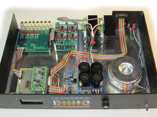
In Circuit Cellar’s January and February 2014 issues, Erickson describes how he upgraded the eight-zone system, which uses microprocessor-controlled analog circuitry. (Like audioXpress, Circuit Cellar is an Elektor International Media publication.) In the end, his project not only improved his home audio experience, it also won second place in a 2011 STMicroelectronics design contest.
Several system components needed updating, including the IR remote, graphic LCD, and microprocessor. “IR remotes went obsolete, so the IR codes needed to change,” Erickson says. “The system was 90% hand-wired and pretty messy. The LCD and several other parts became obsolete and the C development tools had expired. Processors had evolved to include flash memory and development tools evolved beyond the old burn-and-pray method.”
“My goal was to build a modern, smaller, cleaner, and more efficient system,” he says. “I decided to upgrade it with a recent processor and LCD and to use real PC boards.”
Erickson chose the STMicroelectronics STM32F100 microprocessor. “STMicroelectronics’s excellent libraries and examples helped me get the complex ARM Cortex-M3 peripherals working quickly,” he says. “Choosing the STM32F100 processor was a bit of overkill, but I hoped to later use it to add future capabilities (e.g., a web page and Ethernet control) and possibly even a simple music server and audio streaming.”
In the following write-up, Erickson Part 1 provides a system overview, which includes information about its “analog heart”—the crosspoint board. Erikson writes:
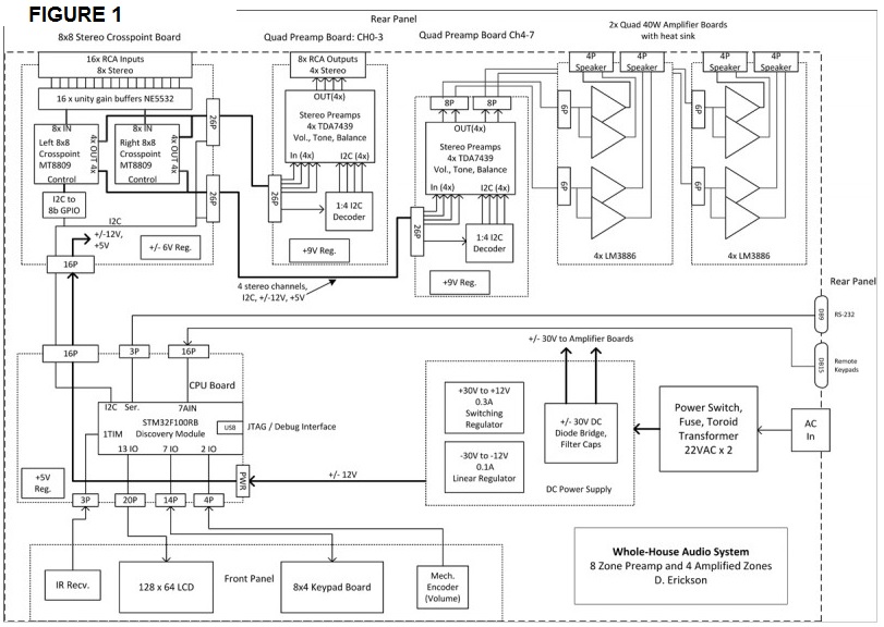
Figure 1 shows the system design including the power supplies, front-panel controls, and the audio and CPU boards. The system is modular, so there is flexibility in the front-panel controls and the number of channels and amplifiers. My goal was to fit it all into one 19”, 2U (3.5”) high rack enclosure.
DIYers dealing with signal leakage issues in their projects may learn something from Erickson’s approach to achieving low channel-to-channel crosstalk and no audible digital crosstalk. “The low crosstalk requirement is to prevent loud music in one zone from disturbing quiet passages in another,” he says.The CPU board is based on a STM32F100 module containing a Cortex-M3-based processor and a USB programming interface. The CPU receives commands from a front-panel keypad, an IR remote control, an encoder knob, RS-232, and external keypads for each zone. It displays its status on a graphic LCD and controls the audio circuitry on the crosspoint and two quad preamplifier boards.
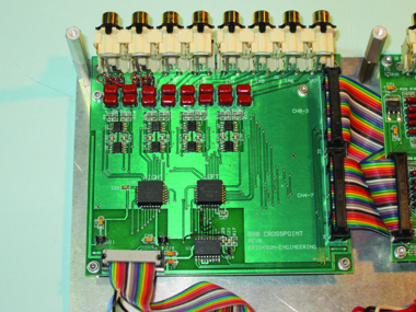
Photo 2 shows the crosspoint board, which is the analog heart of the system. It receives line-level audio signals from up to eight stereo sources via RCA jacks and routes audio to the eight preamplifier channels located on two quad preamplifier boards. It also distributes digital control and power to the preamplifiers. The preamplifier boards can either send line-level outputs or drive stereo amplifiers, either internal or external to the system.
My current system uses four line-level outputs to drive PCs or powered speakers in four of the zones. It also contains internal 40-W stereo amplifiers to directly drive speakers in the four other zones. Up to six stereo amplifiers can reside in the enclosure.
Erickson explains the crosspoint and his “grounding/guarding” approach to transmitting high-quality audio, power, and logic control signals on the same cable:
Erickson's article series about how he upgraded his audio system is now available.The crosspoint receives digital control from the CPU board, receives external audio signals, and distributes audio signals to the preamplifier boards and then on to the amplifiers. It was convenient to use this board to distribute the control signals and the power supply voltages to the preamplifier channels. I used 0.1” dual-row ribbon cables to simplify the wiring. These are low-cost and easy to build.
To transmit high-quality audio along with power and logic control signals on the same cable, it is important to use a lot of grounds. Two 34-pin cables each connect to a quad preamplifier board. In each of these cables, four channels of stereo audio are sent with alternating signals and grounds. The alternating grounds act as electric field “guards” to reduce crosstalk. There are just two active logic signals: I2C clock and data. Power supply voltages (±12 and 5 V) are also sent to the preamplifiers with multiple grounds to carry the return currents.
I used a similar grounding/guarding approach throughout the design to minimize crosstalk, both from channel to channel and from digital to analog. On the two-layer boards, I used ground planes on the bottom layer. Grounded guard traces or ground planes are used on the top layer. These measures minimize the capacitance between analog traces and thus minimize crosstalk. The digital and I2C signals are physically separated from analog signals. Where they need to be run nearby, they are separated by ground planes or guard traces.


