You have just purchased a new solid-state power amplifier for your audio system. The owner’s manual admonishes: “Provide adequate ventilation to allow for dispersion of the heat which is generated by this amplifier. Leave at least two inches above and behind the amplifier. Do not place books or other objects on the unit so that the free flow of cooling air through the slots and openings in the cabinet are obstructed. Do not place near radiators, hot-air vents, or other sources of heat.
“Do not place on a bed, sofa, rug, or other similar surface that may block the cooling slots and openings. Do not install the amplifier in a confined space, such as a bookcase or built-in cabinet, unless proper ventilation is provided. Fan cooling may be necessary in some cases.”
Times Change (Or Do They?)
Why is this? Isn’t modern solid-state equipment supposed to run cool and be highly reliable? Why is the life of electronic equipment so drastically shortened when it becomes hot? The damaging effects of high temperatures generated by vacuum tube equipment seems a little more obvious than they are with solid-state devices.
In the “Olde Days,” you had wax-impregnated paper capacitors. Wire insulation was made of rubber, linen, cotton, and other low-temperature materials. The life of tube filaments decreased as temperatures soared. The need for adequate circulation of cooling air was obvious. You could feel the heat. So why hasn’t the use of modern high-temperature materials and the decreased decreased amount of heat generated by solid-state equipment made these warnings obsolete? Some people suspect that electronic equipment manufacturers design their products for a limited lifetime—one day past the expiration of the factory warranty, for instance.
While the “planned obsolescence” conspiracy theory has been around for a long time, major name brands have reputations to protect. A bad showing in the repair history bar graphs that accompany the product tests in Consumer Reports magazine and its adverse effect on future sales are reason enough for manufacturers to strive for a long operational life.
Why Things Fail
You are much more likely to experience obsolescence from format changes than from the failure of electronic parts. The hardware for erstwhile formats such as Betamax VCRs, reel-to-reel tape recorders, and digital compact cassettes may still perform well, but readily available support for these machines is sometimes difficult to find. Failures in equipment with moving parts (CD players, VCRs, hard drives) are much more common than in those that are purely electronic (amplifiers, computer sound cards, modern tuners).
Mechanical wear is inevitable and is accelerated by dust, vibration, humidity, and other factors against which few consumers bother to take preventative measures. The primary enemies of electronic circuitry are heat, the less-than-perfect structure of all materials used in electronics, and the electrochemical reactions that occur to degrade materials as their temperatures increase. Higher temperatures accelerate the failure mechanisms in all electronic components in an exponential fashion. All components have a basic reliability,
which has its baseline at 25°C.
Above this temperature, the components follow the “10°C” rule, which states that the life of the component decreases by half for every 10°C rise in temperature. If a transistor has a reliability of 1 million hours at 25°C, its expected life will be only 250,000 hours at 45°C. This will decrease to 125,000 hours at 55°C. Few components exist that can withstand more than 125°C.
The temperature in electronic components will rise if you increase the power through the device, or increase the ambient temperature at which you operate it, or both. The ambient temperature for any component will be increased by other heat-producing components that are in close proximity, so the probability of a uniform temperature within a piece of electronics equipment is low.
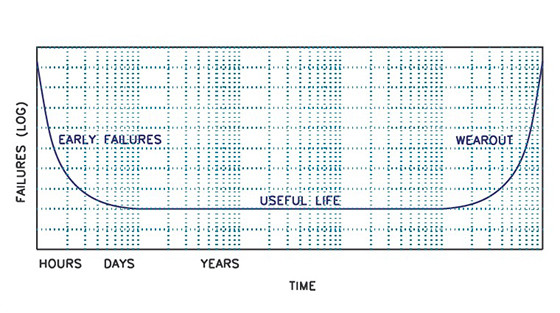
The failures for any electronic device over time follow a typical “bathtub” curve (Fig. 1). There is an initial period of early failures during which defective parts expire. Some manufacturers try to weed out these early failures by means of a limited operational burn-in, and/or incoming device testing, so failures are less likely to occur after the customer purchases the equipment. Depending on the complexity of the equipment, it may take from 2 to 68 hours, sometimes at elevated temperature, to statistically eliminate these early failures.
The flat low-failure portion of the curve represents the useful life of the product. After a certain number of years, the curve begins to slope upward again as wear-out failures begin to occur. All the components have been operating for the same amount of time, so any repairs may be short-lived since additional components may begin to fail as additional “rising-curve” hours are accrued.
Mean Time Between Failure (MTBF)
MTBF is, by definition, the total running hours divided by the number of failures, and is typically expressed in hours. MTBF is a statistical value determined by theoretical calculation or field statistics (see text on page 2: When Will Failure Strike?). Its purpose is to estimate a random value, in hours, of the probability that a failure will occur within a population of equipment, for the environmental and operating conditions under which the data was obtained.
Failure rates apply to equipment with power applied while it is performing its normal intended function. Say a resistor has a failure rate (λ) of 1 × 10⁹ hours. If 50% of rated power is applied, and the case temperature is 40°C, statistically it will not fail for a billion hours. If a piece of equipment uses 1000 of these resistors, you can expect a statistical resistor failure every million hours. Taken to absurdity, a piece of equipment with a billion resistors will statistically see one resistor failure every hour (or 10,000 resistors fail after 100,000 hours).
You can see from this that the published statistical failure rates do not predict reliability or guarantee the operating hours you can expect. It provides the standard by which electronic equipment manufacturers can estimate failure rates using a common set of rules that provide a basis for MTBF comparison. There is a statistical variation for the wear-out life of a piece of equipment as well. In fact, the standard deviation for wear-out life is much greater than the standard deviation of MTBF. As they say in the auto business, “your actual mileage may vary.”
Component Tolerances
All electronic components have a specified allowable deviation from the “nominal” value at 25°C. This deviation is called its “tolerance.” Electrical parameter changes due to environmental variations and aging must be taken into account when designing an electronic device.
A properly designed product will allow for all the worst-case tolerance variations that may occur over the life of the product. Once a component exceeds its maximum tolerance range, it may or may not cause failure or degradation in the operation, depending on the criticality of the component in the overall function.
Mechanical Environment: Shock And Vibration
Most electronic products are subject to vibration and shock at least during shipping, and components that are not securely mounted can short-circuit against adjacent components, or leads and connections may be weakened or broken. Additional steps are needed if components that are designed to be mounted flat on the circuit board are stood on end. Components should also be mounted to preclude dirt and moisture build-up between conductors that might result in short circuits.
Failures can also be the result of electrical, mechanical, or environmental overstress or manufacturing defects. One of the most frustrating failures is erratic operation, which can result from intermittent opens or shorts, insulation breakdown, internal connection defects, component value drift, or instability with temperature. Many TV sets have spent their later years in the repair facility, waiting for the customer’s
complaint to repeat itself.
Capacitors
Despite their simple appearance, capacitors are complex devices. In addition to the obvious parameter of capacitance, they also have series resistance (ESR), inductance (ESL), and parallel leakage resistance (Rp). Capacitors generally come in two types (fixed and variable) and two generic categories (electrostatic and electrolytic). Electrostatic capacitors use inert dielectrics.
Electrolytic capacitors have a very thin dielectric oxide film that is chemically formed on the surface of the electrodes. The capacitance-voltage (CV) product for a given size capacitor is determined by the dielectric constant, or relative permittivity (εr), of the insulating material.
This is the ratio of the permittivity of the material to the permittivity of a vacuum (free space). The dielectric constant is directly proportional to the capacitance and the leakage current. A higher dielectric constant increases the electric flux density, enabling a capacitor to hold its charge for longer
periods of time, and/or hold large quantities of charge. Electrolytic capacitors have very high dielectric constants, while film capacitors have very low dielectric constants.
Failures in capacitors are related to operating temperature, peak voltage stress on the dielectric, peak current in solid tantalum and metallized film capacitors, and the maximum hot-spot temperature. The most prevalent failure mechanism is dielectric breakdown. Most dielectric materials deteriorate with time and temperature and undergo a slow aging process by which they become brittle and more susceptible to microscopic cracks.
Dissipation factor (DF) increases with temperature as well. Insulation resistance (measured in megohm-microfarads, or MΩ-μF) decreases exponentially as the temperature increases above 25°C because of increased electron activity. Low insulation resistance can also result from trapped moisture as a result of prolonged exposure to excessive humidity, or from moisture trapped during the manufacturing process.
The dielectric withstanding voltage decreases as the temperature increases due to the chemical activity of the dielectric material, which causes a change in the physical or electrical properties of the capacitor. Dielectric breakdown may also occur as a result of high voltage transients (surges), causing premature failure. Operating DC rated capacitors at high AC current levels can cause localized heating at the end terminations and separation of the end-connection of the capacitor. This is why care must be taken when selecting a capacitor for AC applications.
Mounting a capacitor by its leads in an environment where it is exposed to high shock or vibration levels may also cause it to open. Military specifications require that components weighing more than one-half ounce not be mounted by their leads alone. The lead wire may fatigue and break at the body connection, so the capacitor body must be fastened into place with a clamp or conformal adhesive.
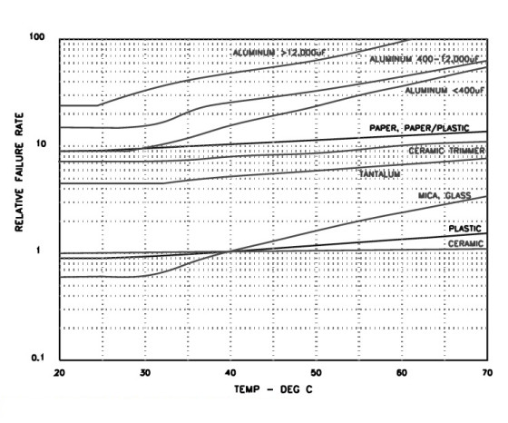
Figure 2 shows the relative failure rates for capacitors versus temperature. Since the baseline specifications for all electronic components are defined at 25°C, the reliability standards do not provide any reduction in failure rate below this temperature. In fact, components such as aluminum electrolytic capacitors may be adversely affected by very low temperatures. Many consumer-grade components are rated for only 0°C to 70°C operation, while Mil-spec parts can be used from −55°C to +120°C.
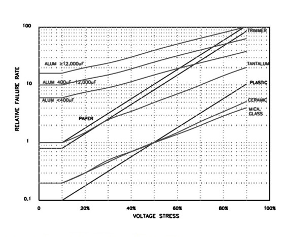
Figure 3 shows the relative failure rates for capacitors versus applied voltage (DC plus peak AC). Note that there is no credit for operating a capacitor (or any other component) at less than 10% of its rating. Even a component with no voltage across it still has a statistical failure rate. Above 90% rated voltage, the chance of failure increases by many orders of magnitude, so none of the reliability standards project failure rate data into this area of operation.
Electrostatic Capacitors
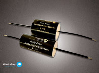
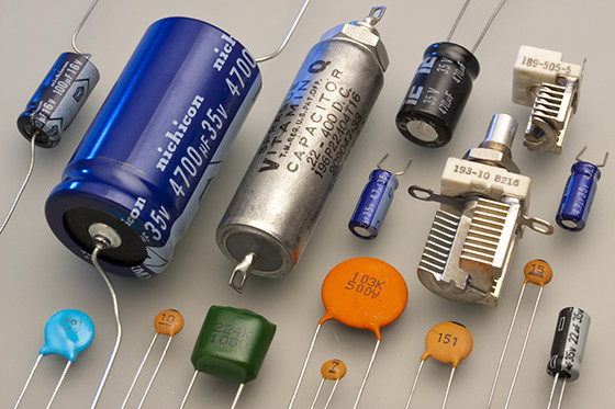
A paper capacitor consists of aluminum foil and a kraft paper dielectric rolled into a cylinder and impregnated with oil, wax, or epoxy resin to exclude moisture. Paper-plastic capacitors add polymers to the kraft paper. Oil-filled paper capacitors generally have higher voltage ratings than other capacitors, from 400 to 5000V.
When a dielectric fault breakdown does occur, the paper is self-healing and leaves little carbon residue that could decrease the insulation resistance. Metal cases are used to contain the oil, and the high voltage types have terminals that are brought out through ceramic stand-offs. They are often used in AC applications such as motor starting and power factor correction.
Since the 1970s, oil-paper capacitors have used mineral oil or synthetic polymer oils. Some of the early paper-oil capacitors are filled with toxic PCBs — be wary of what you buy surplus. Seal leakage is common in poorly made oil-impregnated capacitors. Mechanical failures are caused by fracture of the electrode tab at the point of attachment to the electrode or to the external lead.
Paper capacitors have always been given higher failure rates than the other electrostatic types. This is due to the relatively uncontrolled variations in the kraft paper insulation. There are a number of suppliers who hand-build special paper and paper-oil capacitors for high-end audio. To my knowledge, their long-term reliability has not been established in any recognized standard at this point, but this does not automatically declare them unreliable.
Plastic Film Capacitors
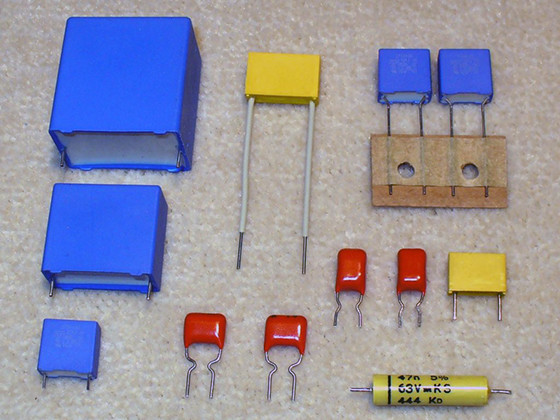
The plastic film capacitor is similar in construction to the paper capacitor. Plastic is much denser than paper, and contamination particles are virtually nonexistent. Plastics can withstand higher temperatures and are considerably more stable than paper.
A number of suitable plastics are available for use as the dielectric in film capacitors. The conductive plates of the capacitor can be either a separate thin metal foil (film-foil), or aluminum can be sprayed directly on the plastic film (metallized). Film-foil capacitors have lower ESR and higher insulation resistance than metallized types, but metallized film capacitors are smaller for the same CV product, and are self-healing if the plastic insulation breaks down.
If a voltage breakdown occurs, and if sufficient current is available, the metallization surrounding the insulation breakdown will burn away, restoring normal operation. In the film-foil types the foil will easily carry the fault current, which will carbonize the plastic and cause a permanent short-circuit. The residual carbon may reduce the insulation resistance somewhat.
The plastics used in film capacitors that are of interest to the audio enthusiast are polyethylene terephthalate (PE, polyester or Mylar), polycarbonate (PC), polypropylene (PP), and polystyrene (PS). Other less-familiar film types are polyphenylene sulfide (PPS), Parylene (paraxylene), polysulfone (PSO), polytetrafluoroethylene (PTFE or Teflon), and polyvinylidene difluoride (PVDF).
For a long time, plastic capacitors were given the same high failure rates as paper dielectric capacitors. In the last 20 years this has changed with the improved processing of polymers and the introduction of advanced engineered materials. Specialty manufacturers have introduced new film and film-foil designs aimed at the high-end audio market.
Polyester film has the highest dissipation factor (DF) of the films commonly used for capacitors. Also, its DF increases exponentially with temperature and directly with frequency, which can lead to thermal runaway in AC voltage applications. Polyester film absorbs moisture (it is hygroscopic), which can decrease insulation resistance and result in unstable capacitance.
Polycarbonate, polypropylene, polystyrene, and Teflon capacitors are very stable and much less influenced by moisture and temperature. PS and PP types are widely used in audio applications.
Ceramic Capacitors
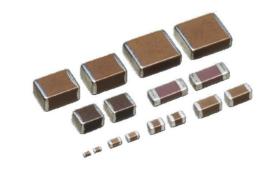
Disc ceramic capacitors consist of special ceramic dielectric materials applied over two or more silver electrode layers, fired at high temperature and encapsulated for protection. Another type of ceramic capacitor is the monolithic type, which consists of silver plates molded with ceramic into a single block. There are three principal ceramic types, with widely different temperature characteristics.
NP0 or COG types are made from non-ferroelectric ceramics. They are the largest ceramics for a given capacitance, but they have very low temperature coefficients (excellent stability). X7R or BX types are made from a ferroelectric ceramic called barium titanate, which changes its crystalline form at elevated temperatures. This structural change causes a change in the dielectric constant that alters the capacitance.
Z5U types have even lower stability, but better packaging efficiency than X7R. Temperature coefficients for NP0 types are very low: ±30ppm/°C. The X7R types vary 15% with AC voltage and up to −25% with DC voltage. The Z5U types vary as much as +22%, −56% over their full temperature range. X7R and Z5U ceramic capacitors have additional undesirable characteristics. Their capacitance decreases exponentially with time. As the applied voltage increases, the capacitance decreases (this is the ferroelectric effect), from 10% for X7R to 50% for Z5U. This characteristic makes them a poor choice for audio, where a varying signal voltage across the capacitor can cause nonlinear distortion.
In DC decoupling applications, the partial polarization of the ferroelectric ceramic persists even after the voltage is removed. General-purpose ceramic capacitors also exhibit piezoelectric effects, in which they can transform mechanical vibration into electrical noise, similar to an electret microphone element. I have also seen large ceramic capacitors develop internal fissures when subjected to high inrush currents.
Dielectric absorption occurs when a voltage reappears across a ferroelectric ceramic capacitor that has been fully discharged. Charge is absorbed into the dielectric due to its dipole moment and the migration of free electrons to its surface.
Ceramic capacitors are generally quite reliable. Most failures are caused by cracks in the materials used to protect the capacitor and lead assembly. Electrical degradation will occur if moisture and contaminants are absorbed between the coating and capacitor plates. Ceramic capacitors do not self-heal like metallized film capacitors.
Mica Capacitors
Mica is one of the best known natural insulators, and mica capacitors are available with voltage ratings as high as 30kV. Silver-mica capacitors have a thin layer of silver deposited on the surface of the mica, resulting in excellent stability and tight tolerance. They are among the most reliable of capacitor types. Like ceramics, most failures are caused by cracks in the capacitor case.
Glass Capacitors
Glass was first used as a capacitor dielectric in the early 1950s, and is available with voltage ratings up to 6000V. Capacitors of this type are characterized by extremely low losses and excellent stability, although the glass cases are fairly fragile.
Variable Capacitors
Air variable capacitors generally have one set of plates meshing between a second set of plates. The capacitance is altered by turning a shaft to vary the overlap area of the movable and fixed plates. The greater the common area, the larger the capacitance. The fixed plate assembly is called the stator, and the movable portion is called the rotor.
Another type of variable capacitor is the trimmer, or padding capacitor. This type of capacitor consists of two or more plates separated by mica dielectric. Tightening an axial screw compresses the plates against the dielectric, increasing the capacitance. Ceramic trimmer capacitors are similar to the air types, except a ceramic-coated metal disc is used as the movable plate. The plates of a variable capacitor are fragile, and short-circuits can occur due to mishandling.
Electrolytic Capacitors
Electrolytic capacitors have electrochemical as well as the usual mechanical failure mechanisms, making them inherently less reliable than electrostatic capacitors.
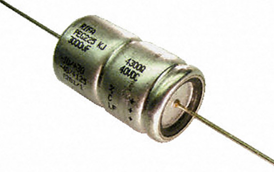
Aluminum Capacitors
Aluminum capacitors are used primarily for power-supply filters. The AC ripple current passing through the capacitor produces a power loss (heating) in the ESR. Aluminum capacitors are also used as coupling capacitors in audio circuits. The ESL makes electrolytics ineffective as capacitors at high (radio) frequencies, where the inductive reactance is very large. There are low-leakage aluminum capacitors available that have been specially designed for audio applications.
The dielectric in an aluminum electrolytic is a thin layer of aluminum oxide that develops on the aluminum foil electrodes during the high-voltage “formation” process. The foil is then wound with a thin paper separator and inserted into the aluminum capacitor case. Finally, an electrolyte of ethylene glycol and ammonium borate is added, which allows the oxide to renew itself during operation.
This chemical nature of aluminum electrolytics causes them to have a limited shelf life — the amount of time the capacitor is stored without any voltage applied, whether in a piece of electronics equipment or in a distributor’s inventory.
The electrolyte gradually evaporates through the case seal. The capacitance and internal resistance continues to drop until the DC leakage current eventually exceeds the limit value for the capacitor. This is the primary wear-out mechanism for aluminum capacitors. If hydrocarbon PC board cleaners are used, they can enter the capacitor and attack the aluminum foil through the end seal.
Modern electrolytic capacitors are more sensitive to ambient temperature than they are to voltage or ripple current (Figs. 2 and 3). It is important to avoid placing high power dissipation near electrolytic capacitors. The internal hot-spot temperature can be quite high in large diameter filter capacitors, so ripple current limits are set by limiting the internal rise to a fairly low 10°C.
It is not unusual for power amplifier manufacturers to connect a number of smaller filter capacitors in parallel to obtain a higher total reservoir capacitance. The I2ESR power loss heating effect is the limiting factor for each individual capacitor in the filter bank. The usual practice is to use capacitors with the same voltage and capacitance so the total allowable ripple current is the sum of the ripple current ratings of the individual capacitors.
Tube amplifier designers, on the other hand, often use filter capacitors in series in order to achieve a specific capacitance at a higher voltage rating than is available in an individual capacitor. The permissible ripple current for the series combination is limited to the lowest ripple current rating of the individual capacitors. Unfortunately, the wide ESR and capacitance tolerance of aluminum electrolytics does not result in equal distribution of voltage across the series capacitors, so they must be shunted with resistors. The current through the shunt resistors should be ten times greater than the rated capacitor leakage current at the temperature at which the capacitors actually operate. Both ESR and leakage resistance will decrease with increasing temperature.
Aluminum capacitors can be reconditioned (the dielectric “re-formed”)3 by applying the rated working DC voltage (WVDC) through a 10W current-limiting resistor over an extended period of time. The predominant failure mode for aluminum capacitors is a short circuit caused by flaws in the oxide film or separator paper that lead to dielectric breakdown. Another life-limiting failure in electrolytic capacitors results from the leakage of the electrolyte due to high internal temperature. Electrolyte leakage is a mechanical failure and is most commonly caused by a deficient compression seal, leakage at the weld on the bottom of the case, or leakage around the aluminum terminals in plastic seals.
Application of a high (greater than 1.5V) reverse voltage will result in a loss of capacitance. An aluminum capacitor can absorb higher reverse voltages for a short period of time, but their failure mode can be explosive when internal pressure builds up after an excessive internal temperature rise.
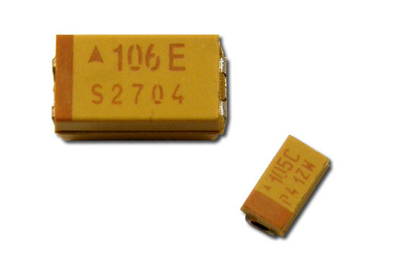
Tantalum
The solid tantalum capacitor is another common type of electrolytic capacitor. Tantalum powder is pressed into a cylindrical shape, then sintered at very high temperatures, resulting in a porous anode. This tantalum surface is electrochemically converted to tantalum pentoxide, which serves as the dielectric. The anode is then coated with manganese dioxide, which serves as the electrolyte in solid form.
Thermal runaway can occur if minute contamination particles such as tantalum carbide are present, preventing the complete anodization into tantalum pentoxide. Local current flow in these oxide faults can increase over time until total failure occurs. Solid tantalum capacitors usually require current limiting of about 3Ω per applied volt (1/3A) to prevent failure due to scintillation effects.
This can also be accomplished by paralleling the tantalum capacitor with a large aluminum cap that limits the rate of voltage rise, thus limiting inrush current into the tantalum
capacitor.
Wet slug tantalum capacitors with silver packages are notorious for major and frequent failures due to silver migration across the dielectric. The silver eventually shorts to the tantalum anode slug. If sufficient current is available, a catastrophic failure can occur due to boiling of the wet electrolyte. Wet slugs should never have a reverse voltage applied to them. Solid tantalum capacitors can withstand limited reverse voltage: up to 15% of rated voltage at room temperature, decreasing to 5% or rated voltage at high or low temperatures.
Next articles continue to survey electronic components, and offer suggestions about how to prevent failure of parts.
This article series was published in audioXpress, from November 2001 to January 2002.
References
1. “Considerations for a High Performance Capacitor,” R. Marsh,
2. “Picking Capacitors,” W. Jung, R. Marsh, Audio Magazine, Feb. 1980, pp. 52–63/Mar. 1980, pp. 50–63.
3. “Electrolytic Capacitor Reforming Unit,” C. Hansen, Glass Audio 6/97, pp. 22–27.
See next page for a discussion on MTBF: "When Will Failure Strike?" >>>


