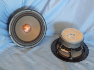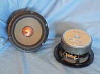


Enter the E0060-08/06, affectionately referred to as the “King Coax,” which is the replacement for the E0057-08/06. The King Coax received its name from the copper ring under the tweeter. When SEAS opened the ring to reduce a dip in the frequency, it resembled a crown. A coax with such good results and a crown, the name King Coax seemed to fit (see Photo 1).
In terms of features, the E0060-08/06 is built on a six spoke cast aluminum frame with six mounting holes that mineralizes any early reflections back into the rear of the cone. Cooling for this driver is primarily provided by the motor mass and the completely open area below the spider (damper) mounting shelf. Attached to the frame is the midrange ring-type neodymium motor structure that powers the woofer and the tweeter. The diameter of the motor is only 2.5” and minimizes reflections back into the midrange cone surface. Heavy copper rings mounted above and below the T-shaped pole piece reduce nonlinear and modulation distortion and increase overload margin. The crown-shaped copper tweeter support ring also eliminates any resonance coming from the cavity between the tweeter body and midrange voice coil former.
Both the midrange cone and the tweeter dome feature a low-mass, surface-treated aluminum/magnesium alloy material. According to SEAS, the midrange cone behaves like a piston throughout the audible frequency range, without any sign of midrange resonances. The cone profile has been designed to optimally load the tweeter’s radiation. A new rubber surround reduces resonances and prevents surround breakup in the midrange band. The surround’s small inverted roll, combined with a profile that follows the cone’s shape, almost totally eliminates diffraction effects on the tweeter’s radiation.


I began testing with the midrange half of this coax driver, using the LinearX LMS and VIBox to produce voltage and admittance (current) curves. I clamped the driver to a rigid test fixture in free air at 0.3 V, 1 V, 3 V, 6 V, and 10 V. Following the established Test Bench test protocol, I no longer use a single added-mass measurement. Instead, I used actual measured cone assembly weight provided by SEAS.
While a midrange driver such as this is likely not to be operating in its piston range, it’s still useful to examine the resonance in the event that you have to employ a LCR conjugate to facilitate designing a passive high-pass (bandpass) filter for the midrange.
I post-processed the 10 550-point stepped since wave sweeps for each sample and divided the voltage curves by the current curves to derive impedance curves, phase calculated. I imported them along with the accompanying voltage curves to the LEAP 5 Enclosure Shop software. I also created a LEAP 4 TSL model using the 1 V free-air curves. I selected the complete data set, the multiple voltage impedance curves for the LTD model, and the 1 V impedance curves for the TSL model in LEAP 5’s transducer derivation menu and created the parameters for the computer box simulations.
Figure 1 shows the 1 V free-air impedance curve (solid black curve) and the tweeter impedance curve (dashed blue curve). Table 1 compares the LEAP 5 LTD and TSL data and factory parameters for both SEAS E0060-08/06 samples.
Parameter measurement results for the SEAS E0060-08/06 midrange were rather close to the factory data except for some minor deviation in the sensitivity. Since everything looked good, I proceeded to set up two computer enclosure simulations using the LEAP LTD parameters for Sample 1. This produced two sealed box alignments — a 500 in3 Butterworth alignment with 50% fiberglass fill material and an 125 in3 Chebychev (Qtc = 1.1) sealed box alignment, with 50% fiberglass fill material.
Figure 2 displays the results for the E0060-08/06 in the two sealed boxes at 2.83 V and at a voltage level sufficiently high enough to increase cone excursion to Xmax + 15% (3.45 mm for the SEAS E0060-08/06). This produced a F3 frequency of 108 Hz (-6 dB = 86.7 Hz) for the 500 in3 box with a Qtc = 0.7, and a –3 dB = 147 Hz (-6 dB = 124.3 Hz) for the 125 in3 box with a Qtc = 1.1. Maximum linear excursion (Xmax + 15%) resulted in 108 dB at 30 V for the larger enclosure simulation and 110 dB at the same 30 V input. Figure 3 shows the 2.83 V group delay curves.
Figure 4 shows the 30 V excursion curves. I did not try to increase the voltage until Xmax + 15% on the smaller box as it just got to a point where the DCR was so high, there would be no increase in SPL for incremental voltage increases.


The explication of the SEAS E0060-08/06 was actually scheduled for the July issue, but other drivers intended for that issue turned out to be defective so I decided to move forward with the SEAS E0060-08/06. However, there was insufficient time to ship the drivers to Patrick Turnmire in Taos, NM, for the Klippel analysis. Since midranges don’t generally operate in the piston range, which is the primary focus of Klippel analysis, I don’t regard it as really essential, but it is interesting to see how balanced the motor system is.
That said, I mounted the SEAS E0060-08/06 in an enclosure that had a 14” × 8” baffle, filled with foam damping material and measured both the midrange and the tweeter’s on- and off-axis frequency responses from 300 Hz to 40 kHz at 2.83 V/1 m, using a 100-point LMS gated sine wave sweep.
Figure 5 gives the SEAS E0060-08/06 midrange on-axis response along with the tweeter’s on-axis response. The midrange has a rising response out to 2 kHz followed by a breakup mode centered on 6 kHz, with a typical second-order low-pass roll-off beginning at 6 kHz. For the tweeter, the response low-pass roll-off begins at 4 kHz, followed by a breakup mode centered on 30 kHz. Obviously, some kind of EQ would be required for the tweeter (e.g., a capacitor in parallel with the tweeter attenuation resistor in a passive network or a shelving network in active DSP).
Figure 6 shows the on- and off-axis frequency response at 0°, 15°, 30°, and 45°. The -3 dB at 30° with respect to the on-axis curve occurs at 1.8 kHz making 2 to 2.5 kHz a reasonable crossover range. Figure 7 shows the normalized version of Figure 6.


Figure 8 depicts the Clio 180° polar pot (in 10° increments). Figure 9 gives the two-sample SPL comparisons for the E0060-08/06 midrange samples, both samples closely matched within 0.5 to 1 dB. For the tweeter, Figure 10 shows the on- and off axis horizontal frequency response out to 45°, with the normalized version shown in Figure 11.
Figure 12 shows the Clio 180° polar plot (processed in 10° increments). Figure 13 depicts the two-sample SPL comparison for the SEAS tweeter, which is within 0.5 to 1 dB throughout the entire frequency range.
I used the Listen AmpConnect analyzer and SC-1 microphone, along with the SoundCheck 15 software to measure distortion and generate time-frequency plots. To set up for the distortion measurement, I mounted the driver rigidly in free air and used a pink noise stimulus to determine the voltage level needed to raise the SPL to 94 dB at 1 m. Then, I measured the distortion with the Listen microphone placed 10 cm from the midrange dust cap and tweeter dome.


Figure 14 shows the distortion curves produced for the midrange (5.33 V). Figure 15 shows the distortion curves for the tweeter dome (5.48 V). Next, I set up SoundCheck 15 to produce a 2.83 V/1 m impulse response for the woofer and the compression driver and imported the data into Listen’s SoundMap Time/Frequency software. Figure 16 shows the resulting CSD waterfall plots for the SEAS E0060-08/06 midrange.
Figure 17 shows the waterfall plots for the tweeter dome. Figure 18 gives the Wigner-Ville logarithmic surface map (for its better low-frequency performance) for the midrange. Figure 19 shows the STFT results for the 1” tweeter.
As one of the premier high-end driver OEMs, SEAS’ products are consistently well-engineered and cosmetically attractive. The E0060-08/06 “King Coax” is great example of the company’s craft.
For more information, visit www.seas.no. VC


This article was originally published in Voice Coil, June 2017.


