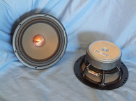

It turns out that Graphene, in addition to the desirable acoustic properties, also works to provide corrosion protection to magnesium. To that end the new Excel Graphene product line has been tested in various places of the world with high humidity, in locations from Singapore to Spain. Second, Graphene, as I mentioned, has also been praised for its sonic properties. Graphene was initially discovered in the 1960s, then re-discovered around 2004 when characterized as a wonder-material, due to its spectacular properties on a Nano scale. To benefit from these properties in our macroscale world, Graphene must be “enabled” to facilitate the application. To put it in layman’s terms, you cannot just sprinkle some Graphene over your loudspeaker and expect an improvement.
The process of developing the new Excel Graphene cones is impressive. The magnesium cones are initially cast, and not stamped out of a flat sheet. To achieve the desired shape and thickness in various parts of the cone, the cones are then machined, followed by the process SEAS has developed to deposit Graphene on the machined surface of the cones (see Photo 1).
SEAS sent us two woofers from the new Excel Graphene product line for our Test Bench — the W16NX003 5.25” midbass driver; and the W18EX003 6.5” midbass driver. In this article we look at the W16NX003 first.


The W16NX003
The Excel Graphene SEAS drivers are pretty much the flagship high-end offering from SEAS and as such have an impressive feature set. For the W16NX003 5.25” midwoofer (see Photo 2), this includes a proprietary injection-molded aluminum frame with six narrow spokes to minimize reflections back into the cone, a lightweight machined cast magnesium/graphene flat profile cone, dual copper shorting rings (Faraday shield), a solid copper phase plug that enhances the shorting ring performance, plus a fairly robust (for a 5.25” driver) 160 W short-term power handling capacity.
Suspension is provided by a radial reinforced NBR surround that reduces radial surround resonance and suppresses surround breakup at high excursion. Remaining compliance is provided by a black flat 3.5” diameter spider (damper). For cooling, the frame is completely open beneath the spider mounting shelf, and with no pole vent, substantial air can be pumped past the copper-clad aluminum wire (CCAW) voice coil and over the front plate.
The motor assembly is powered by a FEA-optimized overhung ferrite magnet motor design. Driving the cone assembly is a voice coil that consists of a 39 mm (1.5”) diameter titanium former wound with CCAW. Voice coil tinsel lead wires terminate to a pair of solderable gold plated terminals.
Testing began with the driver clamped to a rigid test fixture in free-air, and using a LinearX LMS analyzer and VIBox (courtesy of my dear departed friend Chris Strahm) produced both voltage and admittance (current) curves at 0.3V, 1V, 3V, 6V, 10V, and 15V (each sweep with the appropriate 200 Hz tone played between sweeps to progressively heat the voice coil to mimic actual operating conditions). The 15V curves were close to making a useful curve fit, however, I discarded them and post-processed the remaining ten 10 Hz to 20 kHz 550-point stepped sine wave curve pairs for each sample. Then I divided the voltage curves by the current curves, creating the five impedance curves. I applied the LMS phase calculation procedure to the impedance curves and imported them, along with the voltage curve for each sweep, to the LEAP 5 Enclosure Shop CAD program.
Since most Thiele-Small (T-S) parameter data provided by OEM manufacturers is produced employing either a standard T-S model or the LinearX LEAP 4 TSL model, I additionally created a LEAP 4 TSL model using the 1V free-air curves. (Please note that even though LinearX is no longer in business after the unfortunate passing of chief engineer and founder Chris Strahm, LEAP 5 is still one of the best driver parameter generators ever devised in the loudspeaker engineering paradigm, and we will continue to use it until something that is as accurate at predicting high voltage excursion becomes available.)
I selected the complete curve set, the multiple voltage impedance curves for the LTD model, and the 1 V impedance curves for the TSL model in the transducer derivation menu in LEAP 5 and created the parameters for the computer box simulations. Figure 1 shows the 1 V free-air impedance curve. Table 1 compares the LEAP 5 LTD and TSL data and factory parameters for both SEAS W16NX003 samples.
T-S parameter results for the SEAS Excel Graphene 5.25” midbass woofer was rather close to the factory data, with some variance in the Vas and SPL. Part of the variation is due to the difference in Sd calculation, a fairly sensitive parameter. The criteria used for Test Bench is to calculate Sd from the diameter of the cone plus half of the surround width on each side of the cone assembly (the criteria established in LEAP 5). That said, I followed my standard protocol and proceeded to program computer enclosure simulations using the LEAP LTD parameters for Sample 1.
I used LEAP 5 Enclosure Shop to generate the enclosure volumes, which resulted in a 0.37 ft3 Quasi Third-Order Butterworth (QB3) vented box tuned to 41 Hz with 15% fiberglass fill material, and an Extended Bass Shelf (EBS) type vented alignment using 0.52 ft3 tuned to 38 Hz also with 15% fiberglass fill material. Figure 2 depicts the results for the SEAS W16NX003 in the two vented boxes at 2.83 V and at a voltage level sufficiently high enough to increase cone excursion to Xmax + 15% (8.1 mm for the W16NX003). This calculation resulted in a F3 frequency of 55 Hz (F6 = 44 Hz) for the 0.37 ft3 QB3 enclosure and –3 dB = 47 Hz (F6 = 38 Hz) for the 0.52 ft3 EBS vented box simulation.
Increasing the voltage input to both simulations until the maximum linear cone excursion was reached resulted in 107 dB at 27 V for the QB3 enclosure and 106 dB at 25 V input level for the larger vented box. Figure 3 shows the 2.83 V group delay curves. Figure 4 shows the 27 V/25 V excursion curves.


Klippel analysis for the SEAS W16NX003 produced the Bl(X), Kms(X) and Bl and Kms symmetry range plots given in Figures 5-8. As usual, this data was provided by Patrick Turnmire, of Redrock Acoustics, with the DA2 Klippel analyzer courtesy of Klippel GmbH.
The Bl(X) curve for the W16NX003 (see Figure 5) is flat, very broad, and symmetrical, especially for a 5.25” woofer, and with no noticeable tilt. Looking at the Bl symmetry plot (see Figure 6), there is no significant offset, so very good. Figure 7 and Figure 8 give the Kms(X) and Kms symmetry range curves. The Kms(X) curve does have a degree of asymmetry and tilt, with small amounts of both coil-out and coil-in offset. Looking at the Kms symmetry range curve shown in Figure 8, there is 0.74 mm coil-in offset at 3 mm excursion, mutating to 0.57 mm coil-out offset at the 7 mm physical Xmax of the driver, so both numbers are very small. Displacement limiting numbers calculated by the Klippel analyzer for the SEAS W16NX003 were XBl at 82% Bl=7 mm and for XC at 75%, Cms minimum was 5.6 mm, which means that for the W16NX003 compliance is the most limiting factor to reach a 10% distortion level.
Using the less conservative criteria of XBl at 70% and XC at 50%, the numbers are XBl = 8.2 mm and XC = 7.8 mm, both numbers beyond the physical Xmax of the W16NX003. Figure 9 gives the inductance curves L(X) for the W16NX003. Inductance will typically increase in the rear direction from the zero rest position as the voice coil covers more pole area, however, because of the extensive use of copper shorting rings and the solid copper phase plug, inductance decreases in the rear (coil-in) position. From Xmax out to Xmax in, the inductance range only varies by 0.01 mH, which is excellent inductive performance.


plot.

Next I fired up the Listen, Inc. SoundCheck analyzer, using SoundCheck 16 software and the AudioConnect interface along with the ¼” SCM measurement microphone, and set it up for distortion measurements. I set the SPL at 1 m for the W16NX003, mounted in free-air using a pink noise stimulus set to 94 dB (my standard for home audio devices), which required 4.55 V. With the microphone placed at 10 cm from the dust cap, the W16NX003 produced the distortion curves shown in Figure 10.
Following the distortion measurements, I mounted the W16NX003 in an enclosure with a 12” × 8” baffle and made a 2.83 V impulse measurement. This was imported into Listen Inc.’s SoundMap software and windowed to remove the room reflections. Figure 11 shows the resulting cumulative spectral decay (CSD) waterfall plot. Figure 12 shows the Wigner-Ville plot.


Figure 14 illustrates the on- and off-axis frequency response at 0°, 15°, 30°, and 45°. The -3 dB at 30° with respect to the on-axis curve occurs at 2.4 kHz, which suggests a likely crossover point of 2.5 kHz to 3 kHz would be appropriate for the W16NX003. Figure 15 gives the normalized version of Figure 14. Figure 16 shows the CLIO Pocket (courtesy of Audiomatica SRL) generated horizontal plane polar plot (in 10° increments with 1/3 octave smoothing applied). And last, Figure 17 gives the two-sample SPL comparisons for the W16NX003, showing both samples very closely matched throughout the driver’s operating range.
As I would expect, the new W16NX003 Excel Graphene driver exhibits excellent build quality as well as well thought-out design engineering.
For more information, visit the SEAS website at www.seas.no. VC
This article was published in Voice Coil, August 2019.


