The main causes of this are iron core saturation distortion and the winding inductance which bypasses the loudspeaker at low frequencies. Also, the winding resistance typically wastes 10% of the output power. Hence, a lot of iron and copper are required in order to minimize these problems. An alternative is the output transformer-less (OTL) tube amplifier. However, this concept is not easy to realize in practice, otherwise there would be more of these around.
Amplifier Options
My OTL design offers several solutions. First, in order to protect the loudspeakers in the event of a fault, it needed to be naturally current limiting without using auxiliary protection circuits. Another problem was how to realize a symmetrical output stage when tubes do not come as complementary NPN and PNP pairs as with transistors. One option was to adopt the “circlotron” circuit1, which was invented by Cecil Hall in 1951, but that precluded the use of natural current limiting and would have greatly complicated the power supply configuration.
Instead, I designed a non-complementary totem-pole output stage using a novel combination of local feedback and current drive in order to achieve good symmetry and cancellation of even harmonics, as confirmed in subsequent measurements. This configuration has more in common with the Futterman circuit2, except that a long-tailed pair of pentodes is used for the driver stage instead of the concertina phase splitter. The pentodes provide the current drive as well as greater voltage swing than triodes.
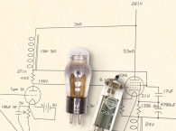
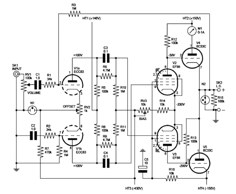
A general aim of the design was to have as simple a circuit as possible with a minimal number of components in the signal path as well as push-pull operation throughout (Fig. 1). Push-pull amplification not only cancels even harmonic distortion, but also provides good rejection of power supply ripple. In a long-tailed pair, the supply current is virtually DC so that the power supply is effectively removed from the signal path.
Above all, I wanted a stable, reliable design that would not need constant readjusting. To this end, I incorporated ample loop DC feedback, which — after initial adjustment — keeps the offset voltage within 20mV between tube replacements. Similarly, the DC bias needs hardly any adjustment over time.
I know that signal feedback is a controversial issue and there are those who maintain that the ultimate goal should be 0dB. However, zero feedback in this design would result in audible noise and an output impedance of 8Ω, which would severely affect the tonal balance of most loudspeakers. I have applied 26dB of feedback, which is a similar amount to most classic tube designs and sets the output impedance to 0.4Ω for well-controlled bass. However, the advantage of a DIY amplifier is that you can adjust the feedback to suit your own taste. The simplest way to reduce the feedback to 11dB is to omit the coupling capacitors between the first and second stages.
Finally, in order to drive normal loudspeakers, I decided that I needed a power rating of at least 20W. The obvious choice of output tube was the Russian designed 6C33C triode, because a single pair can deliver 2.5A into an 8Ω load from a moderate 150V rail. This enables the amplifier to deliver 25W into an 8Ω load or 40W into a 16Ω load, such as my full-range reflex-port loaded Lowthers. If you can increase the load to between 40 and 100Ω, then you can easily obtain 50W of pure class A power.
I could only measure the distortion without feedback (by injecting the signal directly into the grid of the input tube) because the distortion with feedback was less than that of the signal generator. This gave 0.14% THD at 2W with an 8Ω load without feedback, or 0.007% with 26dB feedback. I am pleased to say that, during the eight years since I built this amplifier, only one fault has occurred, which was an internal short-circuit in one of the output tubes. Luckily, the HT fuse did its job and no further damage occurred.
I have designed and built many tube amps over the years from push-pull ultra linear to single-ended triode, using home-wound transformers. I have even experimented with solid-state, but I tend to be highly critical of my own work and have never been fully satisfied with the results until now. This amp just lets me enjoy the ambience and natural tonal color of a real performance. Unfortunately, it is somewhat unforgiving of recent highly compressed recordings, rather preferring early stereo classical and jazz vinyl LPs made with simple tube equipment.
Circuit Details
The signal from input phono socket SK1 is fed to the grid of V1a via the volume control RV1, C1, and R1. Shunt feedback is provided by resistors R1 and R3, which mix the output and input signals to set the overall maximum gain to a value of R3/R1, which is about 29. In other words, an input voltage of 500mV is required to produce 25W into an 8Ω load. When RV1 is set to maximum, the input impedance is about 26k due to RV1 in parallel with R1.
I included capacitor C1 to maximize DC feedback. When there is no offset, the grid of V1a is at the same potential as that of V1b, which is grounded via R4. However, small differences in grid to cathode voltages of each section, due to mismatch, can produce a voltage at the grid of V1a. This also appears across the loudspeaker as a DC offset because the 100% DC feedback path, via R3, keeps the input and output voltages equal. You can adjust trimmer RV2 to null the offset.
An alternative arrangement is to apply the input signal to the grid of V1b with series feedback applied to the grid of V1a. This has the advantage of allowing higher input impedance (1M, for example). However, it would also tend to unbalance the input stage slightly, unless you use an “ideal” solid-state current source in place of R7. Of course, you could achieve excellent noise immunity by using a preamplifier with a balanced output and then applying this to both grids of V1 via C1 and C2.
The input stage, which is formed by V1 and its associated components, acts as a long-tailed pair phase splitter. The high DC voltage across R7 provides a near constant-current that is split between the two halves of V1. This means that if the current through one half increases by a certain amount, the current through the other half must decrease by the same amount in order for the sum of the two currents to remain constant.
As these currents also flow through the anode load resistors R5 and R6, the output voltage developed across one of them must also increase by the same amount that the voltage across the other decreases. An attractive feature of long-tailed pairs is that the current drawn from the supply is near constant DC. In other words, the supply is largely excluded from the signal path, and this reduces its effect on the sound quality.
The neon bulb N1 serves to limit the heater-cathode voltage on both halves of V1 to about 65V maximum during warmup. It is unlit during normal operation. The balanced outputs from the input stage are coupled to the grids of V2 and V3 via C3 and C4. There is also partial DC coupling via R8 and R9. The driver stage, formed by V2 and V3 and their associated components, also acts as a long-tailed pair. The outputs of this stage are directly coupled to the grids of V4 and V5, which form the output stage. Trimmer RV3 allows the voltage developed on the grids of V4 and V5 to be adjusted in order to set the output stage bias current.
The choice of bias current involves a trade-off between tube life and distortion In theory, you can bias the output tubes up to 400mA maximum, at which point their anodes dissipate 60W. This gives the lowest distortion. However, you can achieve a much extended tube life with a lower bias current of, say, 200mA. This also reduces the considerable amount of heat produced by the amplifier!
I used pentodes in the driver stage because they can swing greater voltages than triodes and also because they make excellent current sources. The latter ensures symmetry within the output stage. Another benefit of the pentode is the virtual absence of Miller capacitance between the anode and control grid, due to the presence of a screen grid. This increases the bandwidth of the stage and eliminates the need for frequency compensation components in order to make the amplifier stable when feedback is applied. The only disadvantage is that they produce slightly more odd-order harmonic distortion than triodes.
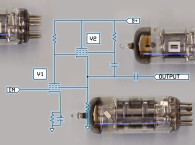
However, the EF86 was designed for audio and, as such, is more linear than, for example, a variable-mu RF pentode. It was used very successfully in the driver stage of the famous Quad II amplifier. You can see the need for a current driver by analyzing the output stage. V4 is a cathode follower. This means that there is 100% negative feedback between the cathode and the grid, which results in less than unity gain and reduced output impedance. V5 is an anode follower and, in order for it to have the same gain and output impedance as V4, it must have 100% negative feedback between the anode and grid. This is achieved by using a current driver, which, by definition, has very high source impedance that does not attenuate the feedback, which is routed via R13.
Although the DC voltages on the anodes of V2 and V3 are not the same, this does not really matter much because, for a given grid voltage, pentodes tend to produce an anode current that is largely independent of the anode voltage. That, after all, is the definition of a current source.
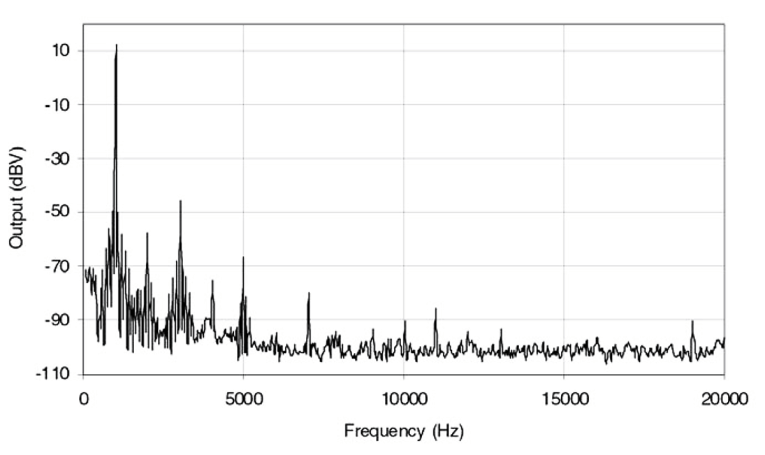
R15 ensures that the grid of V1a is always grounded during warmup, in case no loudspeaker is connected. The gas discharge tube, N2, ensures that the output voltage is kept within safe limits under all conditions. If the output exceeds 90V, it strikes and then clamps the output to a low safe voltage until the output voltage has dropped below this (Fig. 2).
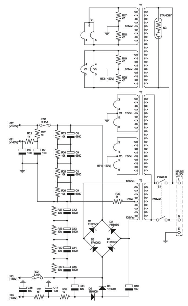
Power Supply
Although the power supply is fairly conventional (Fig. 3) and therefore in little need of description, there are a few points worthy of note: In the event of a fault forcing the output stage latch either up or down, R29 provides a means of limiting the current through the output stage and loudspeaker. If its value were too small, either an output tube or the loudspeaker or both could be damaged.
If its value were too high, a small offset voltage across the loudspeaker could cause a significant imbalance in the supply voltages HT2 and HT4. Fuses F1 and F2 are provided in the unlikely event that both driver tubes, V2 and V3, fail (or not being plugged in), thus causing an excessive current to flow through both output tubes V4 and V5.
In theory, only one fuse is needed, but two are included here in order that any nonlinearity they produce is symmetrical. When connected directly in series with a loudspeaker, fuses are a known source of thermal nonlinearity. At low frequencies, their resistances vary with current to produce harmonic distortion. At higher frequencies, the thermal time constant is such that they produce dynamic compression. However, in this circuit, it is likely that the high internal impedances of V4 and V5 would swamp the small nonlinear resistances of the fuses. Possible improvements to this design could include the use of a DC supply for the heaters of V1 and a delay timer circuit to ensure that HT2 and HT4 are only applied when all the tubes have warmed up.
Practical Considerations
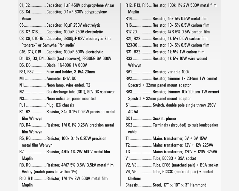
A list of components needed is shown in Table 1. The choice of smoothing capacitors C8-C11 is important because these definitely are in the signal path between the output tubes and loudspeaker and therefore should be of good quality. They should be free of internal vibration, which means that they should not “sing” when the amplifier is driving a dummy load.
Unfortunately, since I fitted the excellent Elna “cerafine" capacitors, they appear to have been discontinued. Instead, I have listed Elna “tonerex” as replacements, although I have never tried them. As for coupling capacitors, I recommend polypropylene for reliability, although you may prefer to use the more expensive paper in oil types. I have been put off by the number of these that I have had to replace in vintage equipment, but I am probably being unfair.
In many places, there are potentially high voltages during warmup, so the resistors must have the correct voltage ratings as well as power handling. The Maplin 2W resistors can withstand 500V DC and are an excellent value, especially because they are sold singly. Also, they sound good, having a low noise floor of 1μV/V and low temperature coefficient of 50ppm/°C.
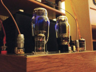
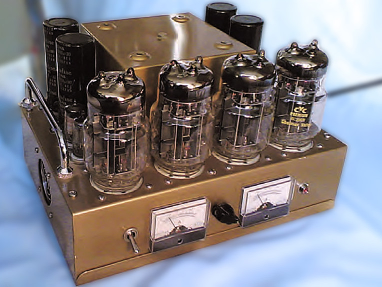
You will observe from Photo 2 that the layout is a little cramped; I recommend using a larger chassis than the 12″ × 9″ × 3″ one that I used. The amplifier produces quite a lot of heat and ideally the tubes should have more space around them for air to circulate. There should also be good ventilation underneath the chassis.
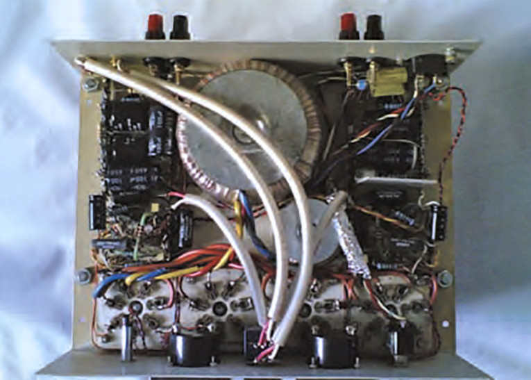
While the retro style toggle switch on the front may look nice, the routing of the wires to it proved somewhat problematic. Notice the aluminum foil that I had to wrap around them to shield the sensitive input stage from the mains frequency radiation plus high frequency harmonics. This is exacerbated by the fact that the current only flows during short pulses while the rectifier diodes are conducting. If possible, fit a rotary mains switch near the back with a long extension spindle or use a relay. I used tag strips throughout because this is a prototype and I knew from experience that design revisions would be likely. Connecting components directly to the tube sockets is generally a good idea because it keeps the signal paths short except in the case of the output tubes because the heat they produce will eventually destroy the component.
Before you switch on, check that the trimmer RV2 is in roughly mid position and that RV3 is set for minimum resistance. It is a good idea to arrange the connections so that this is the most anticlockwise setting. Then you can turn RV3 clockwise to increase the bias current from practically zero to the desired setting (I set it to 200mA), using the ammeter M1. During normal operation, M1 hardly twitches, so it is not a VU meter! However, it is reassuring to have it there as an early warning in case anything goes wrong.
Another good idea is to power up the amplifier the first time without any tubes plugged in just to check all the power supply voltages. After plugging in the tubes and setting the bias current, readjust RV3 if necessary after about 20 minutes. Then connect a millivoltmeter across the loudspeaker terminals and adjust RV2 to zero the reading. Always do this with the volume set to minimum or the input socket shorted.
When the amplifier is working, never switch it on again immediately after switching off or you will probably blow a fuse. Also, it is useful to have an aerosol can of contact cleaner handy because the tube pins and sockets tend to oxidize and will need a cleanup from time to time. aX
This article was originally published in audioXpress, February 2010.
Links to suppliers
www.cricklewoodelectronics.com
RS Components International - www.rs-online.com
www.farnell.com
www.maplin.co.uk
www.chelmervalve.co.uk - Now www.cvc-components.com
Hammond Manufacturing - www.hammondmfg.com
www.wollenweber-audio-modification.de
References
1. C. T. Hall, “Parallel Opposed Power Amplifiers” - US Patent 2,705,265, June 7, 1951.
2. J. Futterman, “A Practical Commercial Output Transformer-less Amplifier,” J. Audio Eng. Soc., (1956 October).
3. Circlotron history page https://circlotron.tripod.com.
For support, discussions, mods, check projects inspired by the original, etc., we highly recommend the DIYaudio forum, which offers multiple threads about this design.
https://www.diyaudio.com/forums/tubes-valves/204960-tim-mellows-otl-project.html
https://www.diyaudio.com/forums/tubes-valves/175247-otl-designed-tim-mellow-4-6c33c.html