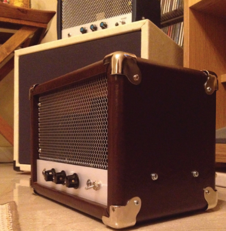
This small amplifier is a medium/high gained head, meant to be played at room or studio levels. Although it can get pretty loud, it can also be played with smooth bass and “quiet drums” on small stages.
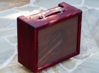
Because of its warm sound, the amplifier isn’t made for any kind of hard metal music. On the other hand it is ideal for blues, rock, jazz, or funk music. The essence of this amplifier is simplicity. That’s what makes it different (see Photo 2).
The Circuit
The music information generated as an electric signal by an electric guitar pickup is weak and needs amplification. Guitar pickups have different output voltages depending on the model. Low-output models tend to produce a “clean” sound, while high-output models tend to overdrive amplifiers and produce a “dirty and aggressive sound.” The output voltage of most pickups varies between 100 mV and 1 VRMS.
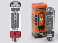
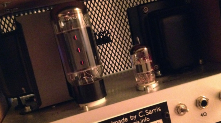
This amplifier uses the high gain 12AX7/ECC83 double triode vacuum tube for the preamp stage, and the 6L6GC beam power tube for the output stage in a single-ended Class-A design.
Class-A amps are voltage amplifiers. In a Class-A amplifier the output voltage’s wave shape is the same with the shape of the signal voltage applied to the grid. In other words, the power tube runs at full power all the time and that affects the way the output tube distorts. A Class-A power amplifier typically sounds warm and natural. When it tends to clip, it sounds dynamic and aggressive. That’s the reason these amplifiers are desirable for many guitarists.
Preamplifier Circuit Design
The preamp stage uses a high gain 12AX7/ECC83 dual triode vacuum tube, and operates as a grounded cathode amplifier. The output is taken from the second half of the 12AX7 triode plate to the power tube’s grid, using a high-quality coupling capacitor 0.1 µF. The driver tube is cathode biased with a 1.5kΩ resistor (R8, R2 shown in Figure 1), and a 200V plate voltage (both stages).

The preamplifier’s first half stage is a fully bypassed cathode bias circuit. The input grid-stopper resistor R12 is 33 kΩ. To bypass the cathode resistor in the first stage (the first half triode), I used a 25µF/25V audio electrolytic capacitor (C2 shown in Figure 1).
The gain potentiometer (1 MΩ) acts as a variable grid resistor to the grid of the second half of the 12AX7 preamp tube. The tone control section consists of a simple “tone boost control” circuit. C6 is the treble-shunt capacitor, so P2 (the tone control pot) affects both the ”tone cut” and the boost. The amount of boost depends on the gain pot’s setting. Tweaking the gain, you can adjust the amount of distortion you want.
The second half of the triode stage can be with or without a cathode bypass capacitor. Decreasing the cathode bypass capacitor’s size, improves the amplifier’s transient response.
While the power tube cathode resistor is fully bypassed (C1, 25 µF/25 V), the power stage needs about a 20-V signal amplitude to be driven to full power. In this circuit, the grid resistor is a variable resistor (1 MΩ master volume pot). So if we use a small size (e.g., 1,000 pF) cathode bypass capacitor in the preamplifier’s second stage, the amplifier’s input sensitivity—with the master volume pot fully open (1 MΩ) — is only 15 mV. That means we only need a 15 mV input to overdrive the power stage! Using a high-output guitar pickup, we can easily overdrive the amplifier to produce the desired “aggressive sound.” Increasing or decreasing the cathode bypass capacitance in the second half of the driver stage, we can improve the tone response, according to our individual taste.
Power Amplifier
In this project, the 6L6GC power tube is running at a 58 mA plate current when no signal is applied, and a 350V plate voltage. The output transformer’s primary impedance 4.5 kΩ. The power tube cathode resistor is fully bypassed by a 25 µf/25V capacitor (C1). The input grid-stopper resistor is 1 kΩ (R1). The voltage across the cathode resistor is measured at 19.5V.
Output Transformer
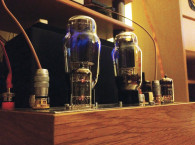
One of the most critical components in the sound path is the output transformer. Therefore, you should never compromise on the output transformer’s quality.
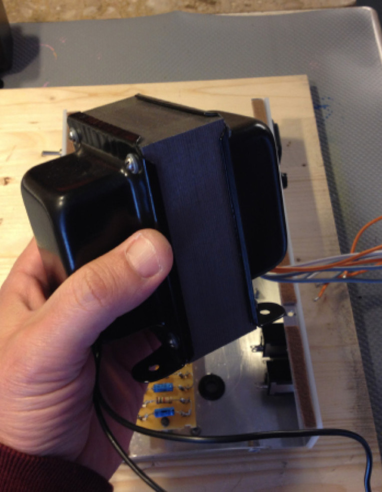
For this amplifier, I chose a custom-made, “E” shaped, high-quality single-ended output transformer (see Photo 3). The resonance-free frequency range for this transformer is much better than 80Hz to 20kHz (–3 dB). The transformer has two secondary windings, 4 Ω and 8 Ω. I also recommend using Hammond Manufacturing’s 125ESE or 125FSE output transformers.
The Power Supply
When designing a single-ended tube amplifier circuit, the power supply section must be carefully considered. For this project, my custom-made power transformer used the following windings:
The primary winding was a 230 VAC (110 VAC in the US)
The secondary windings were 6.3 V/1.5 A filaments for 12AX7 and 6L6 power tube and 260 V-0-260 V/120 mA
Hammond Manufacturing’s 269AX power transformer is a good substitute and can be easily found. The rectifier circuit uses a single section “pi” filter or a “capacitor-input filter.” Both the filter capacitor C11 and the smoothing capacitors C9 and C10 are 47 µF/500V electrolytics. The rectifier bridge circuit in the power supply section consists of two 1N5407 general purpose rectifiers. Filaments are powered with 6.3 VAC for driving and power tubes. For the AC input in the power supply, I used a filtered IEC power input connector (see Photo 4).
Assembling the Amplifier
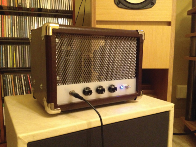
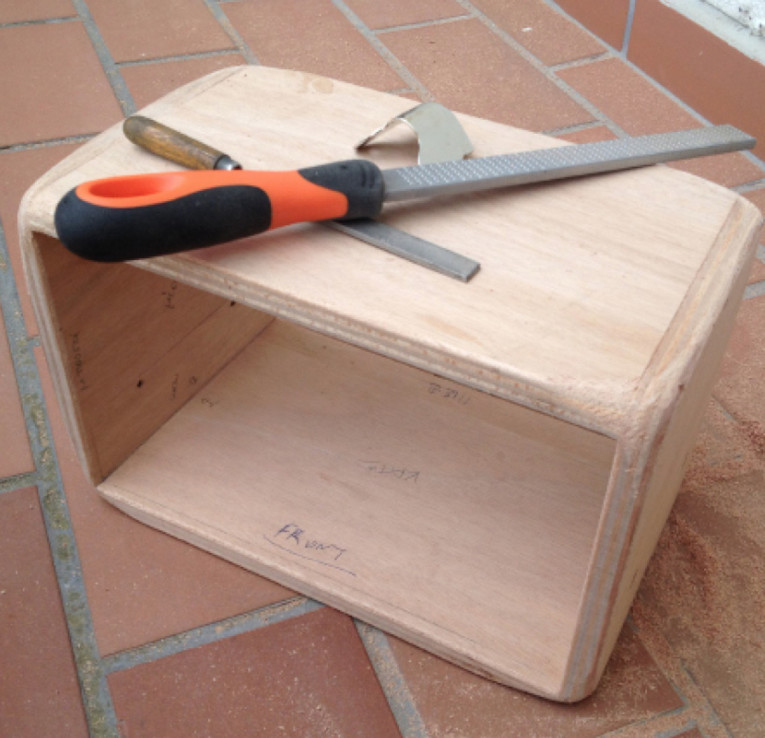
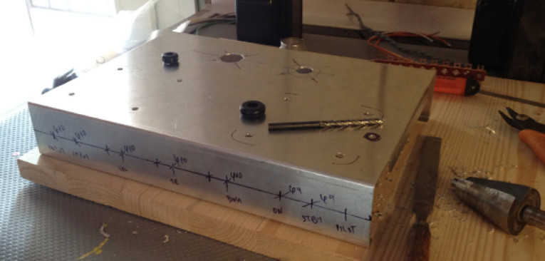
For the amplifier’s construction, I used a ready-made 1.2mm thick aluminum chassis. The dimensions were 25 cm × 15.5 cm × 4.5 cm (W × D × H). I made the wood casing from handcrafted 16mm thick birch plywood (see Photo 5). Then, I covered the wood casing in leather. Tolex or textured vinyl can also be used.
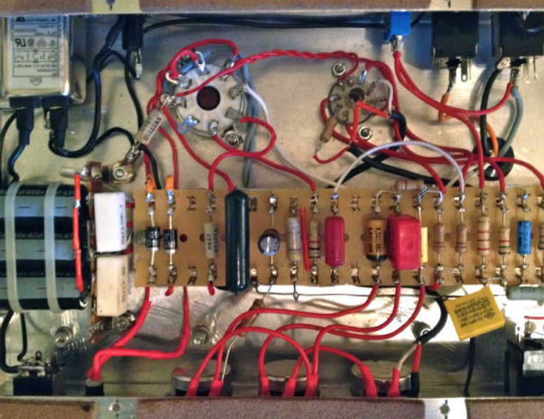
Before the final assembly, I soldered all the parts to the soldering tag board (see Photo 6). All the pots are Alpha 24mm full-shaft 1-M linear.
I installed all the basic components on the chassis (the tube sockets, the output transformer, the power transformer, the pots, the input, and the speaker jacks, etc.). Then, I finished the basic wiring starting with the filaments. I used 1.2mm wire for the ground plane line, and for all the critical paths. All the soldering underneath the chassis, is hand-done, point-to-point wiring using a soldering tag board to place the parts.
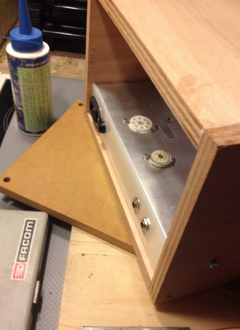
All the power supply parts soldered in a separately tag board, installed in the left side of the chassis underneath the power transformer. To complete the wiring, I connected all the parts directly from the tube sockets and input/output jacks to the tag board (see Photo 7). All the tube sockets were made of high-quality porcelain (see Photo 8). For the final step, I mounted the chassis to the wood casing.
Test Impressions
Two guitarists tested the amplifier. One is Elias Zaikos, a legendary guitarist and founder of Blues Wire (www.blueswire.gr), and the architect of blues in Greek blues scene. The other guitarist and a good friend is George Liagas, owner and designer of Warlord custom pedals (www.guitarpedals.eu). He is also the one who urged me to build this amplifier.
Both guitarists agreed that with 10W of output power, this amplifier rocks with amazing tone, and sounds superb when combined with a good-quality speaker. For our tests, we used a P12R 12” Alnico speaker.
In Practical Application
“Costas Sarris was kind enough to let me try one of his little wonders, and I’m so happy he did that!” said Zaikos. “I’m a working musician, I play tough and hard, electric blues. Guitar sound needs harmonics, tone, bite, and character. His amp gave me the chance to travel from sweet and bold single notes to cutting and exploring double stops and all points between, really nice! To make it short, when you play the blues on the road, all you need is an amp to “hear” you, to feel your touch and express your deepest inner self...and that ain’t easy. Costas’ little amp made me feel like I was playing through an old trusty sonic box. I couldn’t ask for more. Clear and gently or nasty and growling, this was a fantastic experience, Costas, thank you for sharing your work!”
So plug in and rock! Cheers!

Author’s Note:
I would like to acknowledge George Liagas, founder and designer of Warlord custom pedals for his infinite help in testing and fine tuning the amp and Elias Zaikos for his effort testing and tweaking the amplifier. aX
Resources
M. Blencowe, Designing Valve Preamps for Guitar and Bass, Wem Publishing, 2009.
R. Honeycutt, “Tone Controls,” audioXpress, August 2013.
M. Jones, Valve Amplifiers, Newnes, 1999.
RCA Receiving Tube Manual, Technical series RC-19, RCA, 1959.
This article was originally published in audioXpress, June 2015.