A loudspeaker is a mechanically moving system and like any such system, it cannot stop moving in zero time. For example, if a tone is reproduced, and the amplifier outputs a zero voltage at the end of the tone, the speaker cone will not stop immediately but will tend to keep on moving with lower and lower amplitude and eventually come to a stop. In simple terms, the frequency at which the cone is moving on its own is the speaker resonance frequency.
Look at it from a spring view. If the cone is at a certain position away from center when the drive signal is removed or made zero, the suspension will try to pull the cone back to the center position. At reaching center position, it cannot stop in zero time so it will go on moving, shooting through center, and being pulled back again by the suspension, reversing direction and shooting through center again, and so forth, in decreasing amplitudes until the energy has been dissipated and it comes to a standstill. The rate at which this happens is dependent on mechanical parameters of the speaker like the spider and the surround and, to a lesser extent, the air load on the cone.
We don’t want autonomous generation of sound of course, and if we had a way to quickly remove the energy from the system, it would stop quickly. Well, it turns out there is a simple way to remove the energy: electrical damping.
That moving cone has a voice coil attached and, while the speaker is coming to a standstill, that voice coil moves through the field of the magnet structure, generating a voltage at its terminals. If we were able to short-circuit that voice coil during this resonance, the short circuit current would work against the magnetic field and remove energy from the system and bring the cone to a halt! And, if you think of it, we already have a means to shorten the coil: the amplifier output in the described situation is zero, and if it would present a zero impedance to the speaker's voice coil, the voice coil is effectively shorted, and we would be home free!
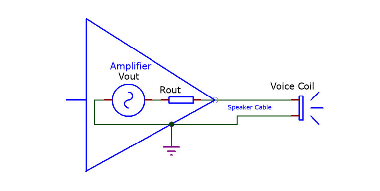
Unfortunately, amplifiers do not have a zero output impedance, although many come extremely close, in the milliohm range. But there’s more stuff between the voice coil and the speaker: speaker cables being obvious, but also, crossover filters may represent an impedance at the resonance frequency. And of course, the voice coil itself has a resistance that is in the circuit, limiting the short-circuit current.
Speaker and amplifier designers have come up with a metric to quantify the amount of electrical speaker damping in any given situation: the impedance you see when looking into the speaker terminals, divided by the impedance you see when looking outward from the speaker terminals toward the amplifier. That ratio is the damping factor (DF).
Let’s take an example and limit ourselves to low frequencies where the impedances are close to the resistances, for a speaker with no crossover filters. Looking into the speaker terminals, in a typical 8Ω speaker we see something like a 6.5Ω voice coil resistance. Looking from the speaker terminals toward the amplifier we see speaker cables with, say, 100mΩ total resistance, and an amplifier output resistance of say 0.5Ω. Thus, DF is 6.5/(0.5 + 0.1) = ~10.8. And, even if we had an ideal amplifier with zero output impedance, the speaker cables would limit the maximum DF to 65.
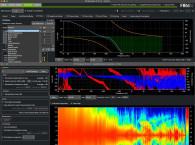
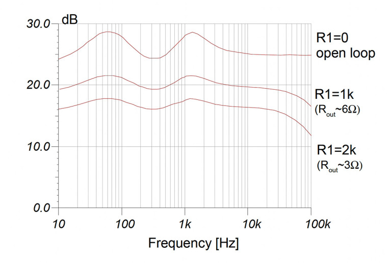
More importantly, does it matter? If the speaker is insufficiently damped, it will impose its own response on the acoustic output. We looked only at the fundamental resonance frequency, but there are often many resonances at other frequencies and the mechanisms are the same. Ian Hegglun [1] did some work on the effects of amplifier output impedance (and thus DF), which shows that the lower the DF, the more the speaker resonances are suppressed (Figure 2; disregard absolute level differences). His amplifier output resistance values are relatively high, and lower values will flatten the response even more. In the industry, it is generally assumed that a DF of 20 is high enough to make speaker-imposed response variations inaudible.
So, now you know why that single-ended tube amp with 3Ω output impedance sounds much different with different speakers, than the high-feedback solid-state amp with 0.25Ω Rout does!
Reference
[1] I. Hegglun, “Square-law class-A: a family of efficient class-A power amplifiers,” Linear Audio Volume 1, June 2011, available from Amazon.
This article was originally published in The Audio Voice newsletter, (#451), January 4, 2024.