We are happy to rely on these results, which might raise eyebrows with our more academically minded colleagues. What? No Double-Blinded Trials (DBTs)? To which we would respond, have you heard the examples? DBTs are crucial in establishing whether a small impairment is audible. That’s not the point here. Loudspeakers aren’t known for the subtlety of their distortion. We wanted to know which kind of impairment is worse once it’s large enough to be indisputably audible. As engineers, we just want to get our priorities right. Nothing more refined was needed to decide which problems to tackle first.
Nonlinear Parameters: Not Just for Nerds
All too few datasheets have Bl(x) and Kms(x) curves in them. That needs to change. How else is a speaker designer to know what purposes a driver will be good for? For example, suppose a driver’s suspension is so linear that the voice coil can easily leave the range where Bl is constant. That rules out its use in a two-way speaker because a loud bass tone will immediately cause audible burbling in the mid-band. For a midwoofer, you’re looking for something with a progressive suspension that gradually limits excursion before Bl drops off. That reduces ugly AM caused by a varying Bl and trades it for an increase of much less ugly straight harmonic distortion in the bass.
Force Factor Modulation
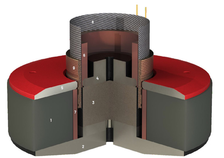
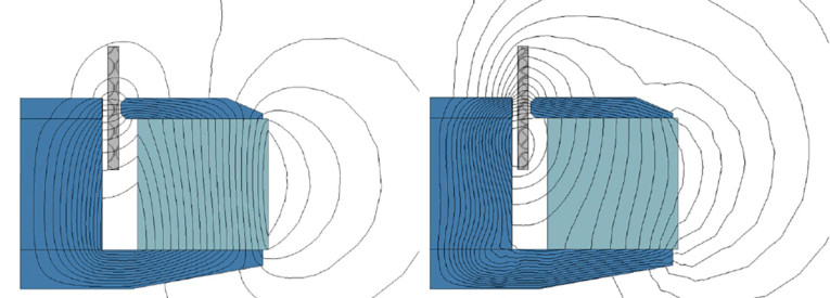
Several ways are known to get a flatter Bl(x) curve. Some modify the gap geometry. Others, like ours, modify the winding geometry. Bl is not solely dependent on position, however. Current plays just as big a role. The voice coil produces its own magnetic field, which is superimposed on the field generated by the magnet (Figure 1). Field lines caused by windings below the pole plate will close through the gap. This unwanted flux adds to or subtracts from the wanted permanent flux (Figure 2). We call this Force-Factor Modulation (FFM).
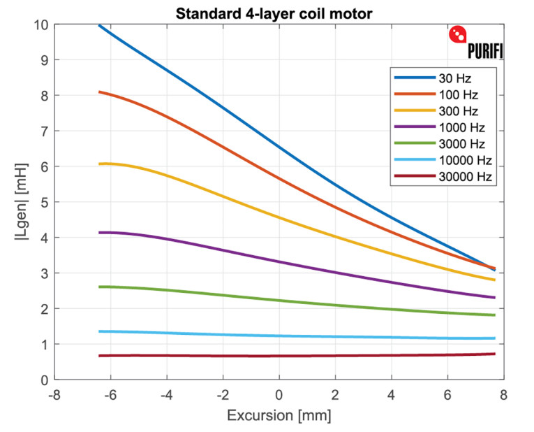
Long voice coils exacerbate the problem. It is not unusual to see 50% modulation in compact, long-stroke units. Fixing FFM is as important as flattening the Bl curve (Figure 3).
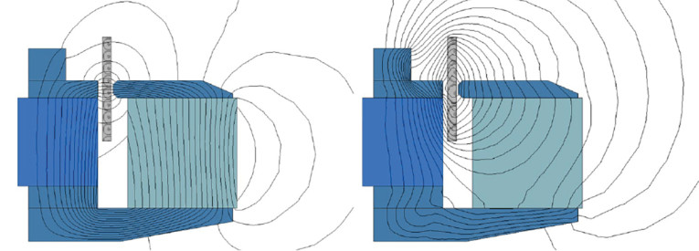
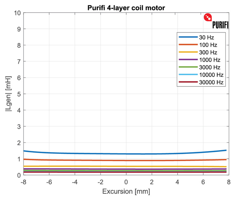
So far there is no agreed way of specifying FFM. For reasons that are as arcane as they are fundamental [3], FFM is equivalent to saying that the electrical inductance changes with position. Electrical inductance is a familiar parameter, which is why we like to specify FFM as a family of curves (Figure 2 and Figure 4) showing voice coil inductance as a function of position, with frequency as a parameter. The slope of the curves is an expression of FFM.
Plotting electrical impedance at different cone positions, however, is not that useful. At low frequencies, the DC resistance squarely hides the inductance. Diagnosing low-frequency FFM from such graphs is all but impossible. As a result, few people are aware that shorting rings are useless in subwoofers. With shorting you can correct the position-dependent inductance at 1kHz. You can also make it worse. At 50Hz you can do neither. Even copper has too much resistance to counteract low-frequency flux changes.
Current drive is sometimes proposed as a fix, but the equivalence of FFM and inductance variation means that current drive only solves half of the problem. The electrical inductance appears not once, but twice in the equivalent model of a loudspeaker. First explicitly in series with the voice coil, then again implicitly as the current-dependent variation of the force factor! A driver that has no FFM will automatically have a constant electrical inductance.
Eliminating FFM
A so-called “iron-free” motor is inherently free of FFM. Permanent magnets are fully saturated. Their AC permeability is pretty much that of air. On the downside, it costs a fortune in magnets and without iron you can’t focus the magnetic field. That makes it harder to control the shape of the Bl(x) curve.
Our preferred solution works in two steps. The first is to take inductance down by reducing the permeability of the pole. FFM is determined by the absolute change in inductance versus position, not the relative change, so reducing inductance is a good start.
It’s tempting to do so (as some do) by using a bigger magnet to saturate the pole. That works, but only at low signal levels. For any realistic magnet, it won’t take much drive current to take a saturated piece of iron back out of saturation. When that happens, inductance rockets up. This strikes us as a clear case of voluntary podal ballistics. Instead, we replace most of the pole outright with a piece of pre-saturated material (i.e., a permanent magnet).
At this point, the inductance still goes up for negative excursions, but only by a small amount. The second step is counterbalancing this with a piece of unsaturated material set on top of the pole. In terms of gap geometry and DC field, the resulting design is entirely standard. Only the AC field shows a dramatically different picture, with field lines no longer returning through the air gap. The inductance curves shown in Figure 4 confirm that FFM has effectively been eliminated. In terms of assembly, the only headache is that the pole (a neodymium magnet) needs to be installed after both it and the ferrite ring have been magnetized.
Sd Modulation
The sensitivity of a driver is proportional to Bl and Sd, and inversely proportional to Mms. Nothing else. Having made Bl constant over position and current, are we now free of AM? Not quite…It amuses us to note that the audio field is frequently abuzz with new and exotic cone materials that everyone must have. The newest marvel crafted from Obscurium Unobtanate is then fixed into a basket using a bit of rubber, a practical necessity that is not otherwise mentioned.
And yet, we quantify Sd by measuring the diameter halfway up the roll. A 5” driver with an Sd of 80cm2 and an 8mm wide surround is 55cm2 worth of actual cone with 50cm2 worth of surround attached, of which an “effective” 24cm2 is presumed to move. How is that going to be negligible?
The reality is grisly, as a bit of poking around with any driver will show (Figure 5). Push the cone up and most of the surround becomes immobile. Push the cone down and most of the surround follows. Vice versa for an inverse roll. Our example has an Sd that varies between 105cm2 and 55cm2, directly translating into a 6dB sensitivity change. Once again the bass, which supplies most of the movement, causes AM of the entire signal. Complicating matters further, if a varying proportion of the surround moves with the cone, Mms is also not constant!

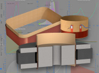
Short of trying not to use a surround, there aren’t many options. We chose to construct an “Sd-neutral” surround, where alternating normal and inverse roll segments cancel out each other’s Sd variations (Photo 1). The tricky bit is transitioning between them without producing torque or torsion on the cone. The W-folds and dimples are co-optimized to minimize the problem.
Hysteresis
Even if we don’t think it helps against FFM, we use a lot of shorting. This is mostly done to eliminate mid-band distortion caused by hysteresis in the remaining iron parts. As anyone who has experimented with current drive can attest, its most spectacular effect is a reduction in distortion for pure midrange signals. A 15dB reduction in, say, the 300Hz to 2kHz region is quite normal. This shows that for this frequency band the dominant distortion source is something that specifically affects the electrical impedance. This turns out to be the iron in the magnetic circuit.
We’ve recorded and plotted some actual waveforms [4] to illustrate just how peculiar hysteresis distortion is compared to ordinary nonlinearities. Shorting rings are very effective here. They shield the iron parts from the AC field emanating from the voice coil. Not at low frequencies of course, but there we had bigger fish to fry. The current harmonic distortion (HD) plots in our datasheets can help the user estimate how much hysteresis distortion is left.
Conclusions
•Distortion mechanisms in loudspeakers that manifest as amplitude modulation are highly audible.
•Kms(x), Bl(x), Force Factor Modulation, Sd(x) and Mms(x) all directly impact sound quality in a straightforward manner.
•Of these, Bl(x) and Kms(x) are already industry standard parameters. They belong in all loudspeaker datasheets.
•We propose to specify FFM as the change in electrical inductance versus position, with frequency a parameter.
•Sd(x) and Mms(x) currently fly under the radar. A practical test method is needed so they can be added to the datasheet. VC
References
Purifi Audio - www.purifi-audio.com
[1]“Doppler distortion vs IMD?,” Purifi Audio, https://purifi-audio.com/2019/12/07/amfm
[2] “Low frequency harmonic distortion is almost inaudible. So what’s the point of low distortion drivers?,” Purifi Audio, https://purifi-audio.com/2019/12/12/imd
[3] Risbo, Lars; Agerkvist, Finn T.; Tinggaard, Cartsen; Halvorsen, Morten; and Putzeys, Bruno, “Force Factor Modulation in Electro Dynamic Loudspeakers,” Audio Engineering Society Convention Paper, September 2016, https://purifi-audio.com/wp-content/uploads/2019/12/PURIFI-AES-9607.pdf
[4] “This Thing We Have About Hysteresis Distortion,” Purifi Audio, https://purifi-audio.com/2020/04/28/dist
This article was originally published in Voice Coil, August 2021.