By Brian Johansen, Per Rasmussen, and Morten H. Pedersen (GRAS Sound & Vibration)
As higher demands are placed on the sound quality of in-ear headphones, more and more advanced solutions are being developed, and they in turn require more sophisticated measuring equipment during development.
For this purpose, various ear simulators have been introduced by vendors over time, covering the full human audible frequency range. They include the 60318-4 IEC standardized Ear Simulator (100Hz to 10kHz), the enhanced GRAS “711” High-Frequency Ear Simulator (100Hz to 20kHz), and the ITU-T recommended Type 4.3 Ear Simulator (20Hz to 20kHz). There is an increased interest in the high-frequency spectrum in the human ear canal, but also things such as leak and placement are emerging as very important factors for device performance and performance measurements.
In addition to the attempt to create a “one size fits all” ear simulator that, in reality, fits no one but simply represents an “average ear” geometry, there is a rarely explored dimension at play. Studies have shown that the success criterion for headphones (especially in-ears) is not solely determined by evaluating the frequency response between the in-ear transducer and the ear simulator.
Instead, the listening experience is largely influenced by how the pressure field is built up in the semi- or fully closed ear simulator, hence leak and insertion position become overshadowing parameters.
So, in an attempt to solve some of the immediate problems, new complications arise making it challenging to ensure consistency and repeatability when characterizing in-ear devices.
Pressure acoustics frequency domain simulations using the COMSOL Type 4.3 Ear Simulator with various ear canal shapes were conducted to assess the impact of different ear canal geometries. The modeling begins with the specific geometry defined in ITU-T Rec. P.57 Type 4.3, assuming the in-ear headphone is positioned inside the ear canal, stopping short of the reference plane for practical reasons.
Transfer Impedance and the Sound Source
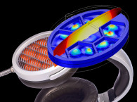
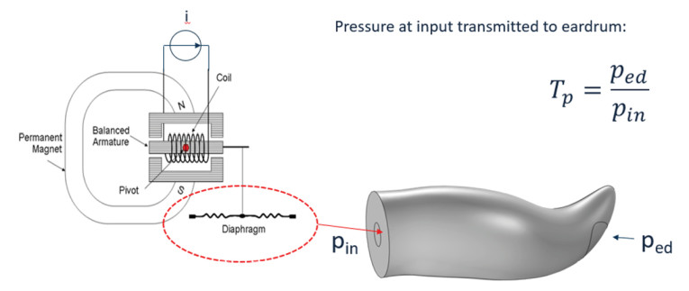
The basic defining parameter for an ear simulator is the transfer impedance and this is often measured using a measurement microphone as a sound source (Figure 1). For this type of source, the diaphragm deflection will be proportional to the input signal and the source will act as a constant deflection source. This means that the velocity of the diaphragm will increase proportionally with the frequency.
The transfer impedance is defined as the resulting sound pressure at the eardrum position divided by the volume velocity at the input plane. To account for frequency proportionality and obtain the genuine transfer impedance, the obtained signal needs to be divided by frequency. This measurement reflects how it would have been assessed had a constant volume velocity source been utilized instead of a constant displacement source.
While a capacitive-type transducer (e.g., a measurement microphone) operates as a constant displacement source, a standard earphone speaker tends to behave more like a constant pressure source. A dynamic transducer equipped with a coil in a magnetic field generates a force proportional to the current in the coil, resulting in a consistent pressure on the diaphragm independent of the load.
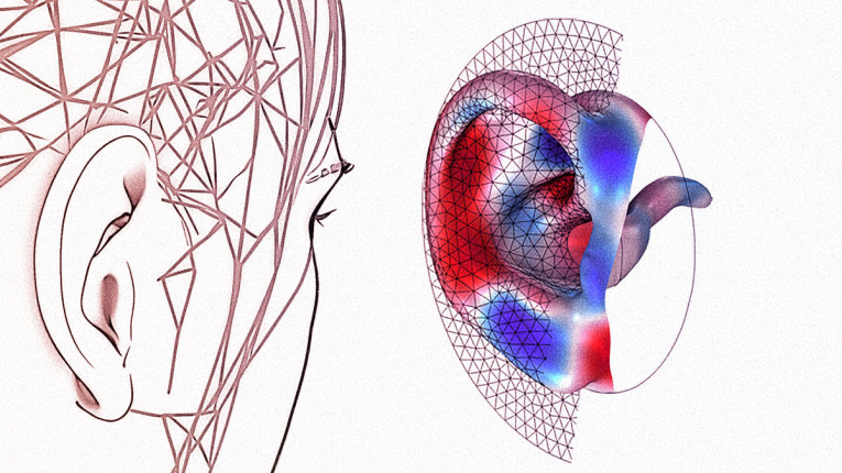
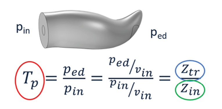
This implies that the input to the ear simulator is not a constant velocity signal but, rather, a constant pressure source, or even somewhere in between. Consequently, it is more pertinent to examine the pressure transmission from the input area to the eardrum region (Figure 2).
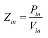
It is therefore important to know the input impedance of the ear simulator, as this defines the relationship between the pressure at the input area and the particle velocity in the same plane:
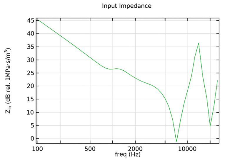
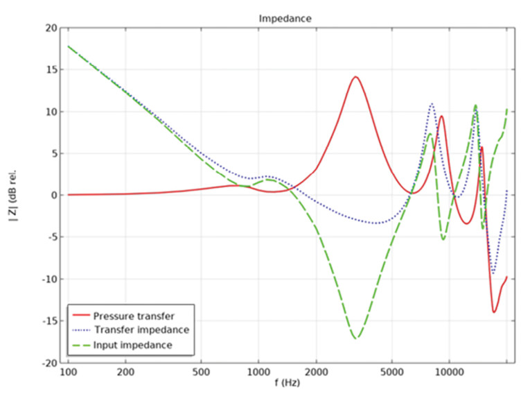
The pressure transfer curve can be used to calculate ped (pressure at the eardrum) from pin (input pressure) illustrated by the red curve shown in Figure 4. It is noteworthy that the dip in the input impedance (green) significantly impacts the pressure transfer, leading to a peak somewhere between 2kHz to 5kHz, influenced in this case by the quarter wavelength resonance in the ear canal.
It is common for ear simulators to be specified with dimensions (length and volume of the ear canal segment) as well as a transfer impedance in various literature and standards (IEC, ITU-T, ANSI, etc.). The transfer impedance thus encompasses the characteristics of the physical nature of the ear canal and the ear drum simulator, where the ear drum simulator plane ideally includes the mechanical impedance of the eardrum and middle ear (Figure 4).
The transfer impedance will to a certain degree be influenced by the actual design of the device under test (DUT). However, the input impedance and pressure transfer from the active sound generating plane in the DUT is often more dramatically influenced by the specific design of the earphone sound outlet part. This includes the hole size and length of the cavity in front of the active element. Specifically, the length of the active ear canal determines the high frequency resonances. For the transfer impedance, the first resonance is half- wavelength.
However, for the input impedance and thereby also for the pressure transfer, the quarter-wavelength will determine the first resonance frequency, and this will be at lower frequency. Thus, if the transfer impedance’s first resonance is at 12kHz, the first input resonance will be at 6kHz. Therefore, the influence of the effective ear canal length will be seen at lower frequencies for the input impedance and the pressure transfer than for the transfer importance. This in effect makes the positioning of the DUT in the ear canal even more critical than the analysis of the influence on the transfer impedance below indicates.
It is the input impedance of the ear simulator that loads the DUT. Because what we really want to ascertain using ear simulators is how robust our DUT is when subjected to the mechanical load of a human ear. That is the entire purpose and essence of Ear Simulator testing.
The following simulations are conducted employing the COMSOL integrated 711 Ear Simulator and ear models.
The Shape of the Ear Canal
The well-known IEC 60318-4 ear simulator has a section of the ear canal of approximately 12mm in length, represented by a straight cylinder. The recently defined ITU-T Rec. P.57 Type 4.3 Ear Simulator has a “human-like” ear canal with a length of approximately 17mm to the reference plane. This implies a reference plane farther away from the eardrum simulator than before, possibly better reflecting the distance at which one typically places an in-ear headphone. It is understood that the canal is shaped like an “average human ear canal,” made to mimic the human ear with its distinctive bends rather than a mechanically simpler design.
Therefore, it is interesting to examine whether the transfer impedance changes as a function of the canal’s geometric complexity.
To be able to change the geometry during the simulations, the ITU-T geometry is approximated by a parametrized model, which can be described as a mathematically defined surface. The parametrized model can easily be changed in length, volume, and shape to investigate the effect of these parameters (Figure 5).
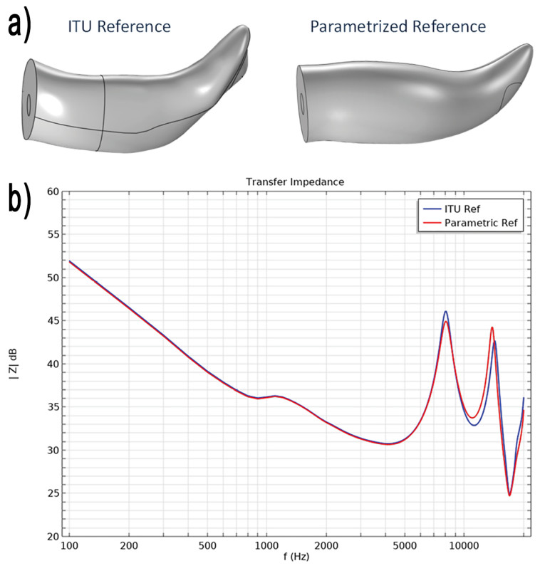
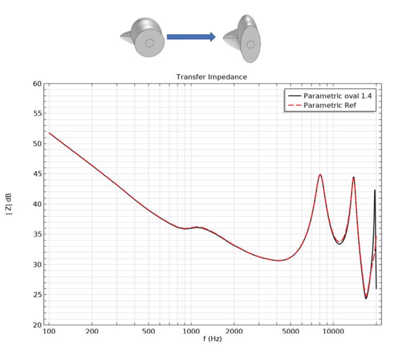
If we instead make the ear canal cross-section more triangularly shaped it does not change the transfer impedance (Figure 7) and if we straighten the ear canal it does not change the transfer impedance much either (Figure 8) except for the change due to the slightly decreased length of the canal.
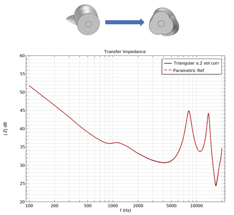
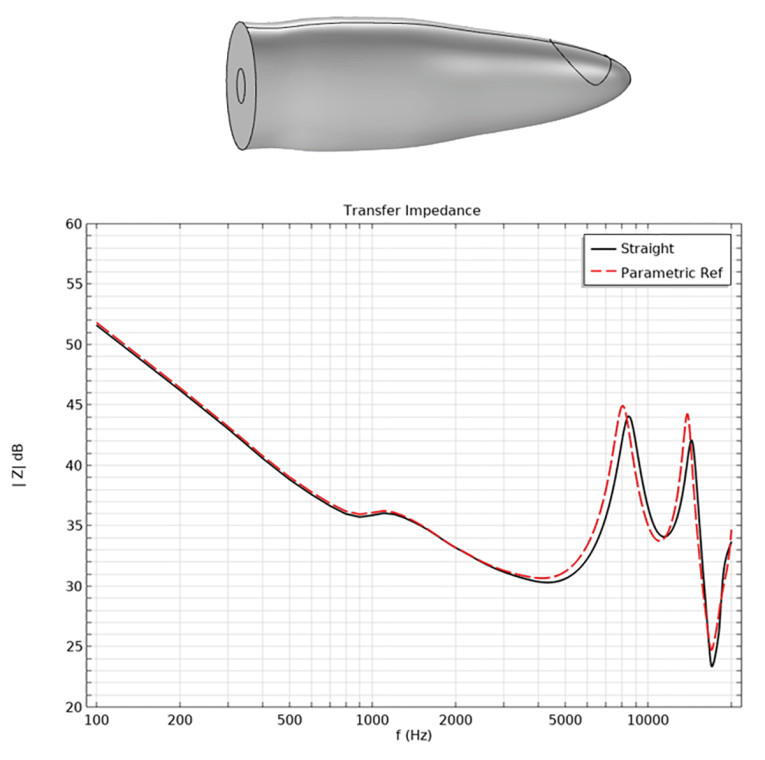
The conclusion drawn is that, fundamentally, it matters little whether the canal is straight, cylindrical, oval, triangle-shaped or “human-like” with bends.
The Ear Canal Size
Now we have observed the impact of altering the shape of the ear canal, where its length and volume have been fixed. But what happens if we modified these dimensions, considering that individuals have varying volume sizes of their ear canal, and the length is defined by the insertion depth of the DUT?
If we increase or decrease the ear canal volume the transfer impedance changes quite a bit (Figure 9). In the frequency range from 2kHz to around 6kHz, the transfer impedance is increased when the volume is decreased and decreased when the volume is increased. The same is true below around 1kHz but less pronounced as the relevant ear canal volume in this range includes the middle ear volume behind the ear drum and this has been held constant in this simulation. It may be argued that if a person has a large ear canal, maybe the middle ear volume would also be larger, but this has not been considered here.
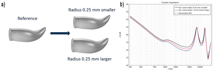
It can also be seen that the positions of the resonances at 8kHz and 16kHz are not affected by the volume changes as these are defined by the distance between the input plane and the eardrum.
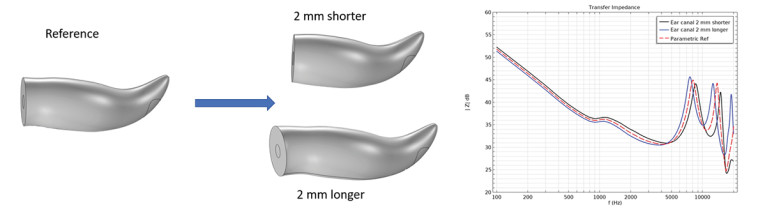
Positioning and Measurement Results
If we change the insertion depth for the DUT by ±2mm from the reference plane in the ITU-T 4.3 ear simulator, we get quite different results (Figure 10). At low frequencies the transfer impedance changes as the volume increases due to longer length as described above. At high frequencies the position of the resonances in the transfer impedances is shifted due to the changed length between the source plane and the ear drum position.
This means that the transfer impedance is very sensitive to the exact position of the DUT in the ear canal, as a position slightly outward will increase the volume and distance and, similarly, a slightly deeper position will decrease the volume and length. A side effect of the more “human-like” ear canal shape is that the exact position of the DUT in the ear canal is less well-defined resulting in less well-defined transfer impedance, which also makes it more difficult to compare measurement results.
Conclusion
When testing in-ear headphones in ear simulators one of the main concerns is the positioning of the DUT in the ear canal. This will define the ear canal volume and length for the test and thereby the acoustical properties of the ear simulator. If the position of the DUT varies from test to test, or varies for different implementations of the DUT, then the results from an ear simulator test may not be easily compared. Similarly, the performance of an in-ear headphone in a real human ear will depend on the exact position in the ear canal and thereby the resulting effective volume and length of the ear canal.
The actual precise shape of the ear canal, both for an ear simulator as well as for a human ear canal, is of minor influence, if the volumes and lengths are well defined. A further complicating factor in the low-frequency response is the influence of leaks between the DUT and the ear canal surface. With complicated ear canal geometry, it becomes difficult to achieve the same leak from test to test and therefore difficult to evaluate effects of design changes or modifications. aX
Resources
“Type 4.3 Ear Simulator,” COMSOL,
www.comsol.com/model/type-4-3-ear-simulator-106741
About the Authors
 Brian Johansen, R&D, has more than 20 years of experience in the acoustics industry. He has tested sound in everything from airplanes and cars to refrigerators and satellite launches. Brian is the inventor of the “human-like ear simulator” that revolutionized the personal audio (cell phones / headphones / earbuds) industry, and holds a number of other patents for inventions in the acoustics field.
 Per Rasmussen M.Sc. Acoustic Consultant, has more than 40 years of experience in the design and application of measurement microphones for a wide variety of industries including automotive, aerospace, and consumer electronics. This includes applications ranging from measurements on cars, aircrafts, drones, impulsive noise sources, wind tunnel measurements, headphones, and more. Per is the son of Gunnar Rasmussen who founded GRAS, and was co-owner and director of the company until 2020.
 Morten Høgholm Pedersen, Vice President Product Management, has 25 years experience in medical device development and research within ultrasound, audiology, hearing aid fitting and medical software in both R&D and product management roles. Morten currently heads up GRAS’ Sound & Vibration product management.
This article was originally published in audioXpress, April 2024