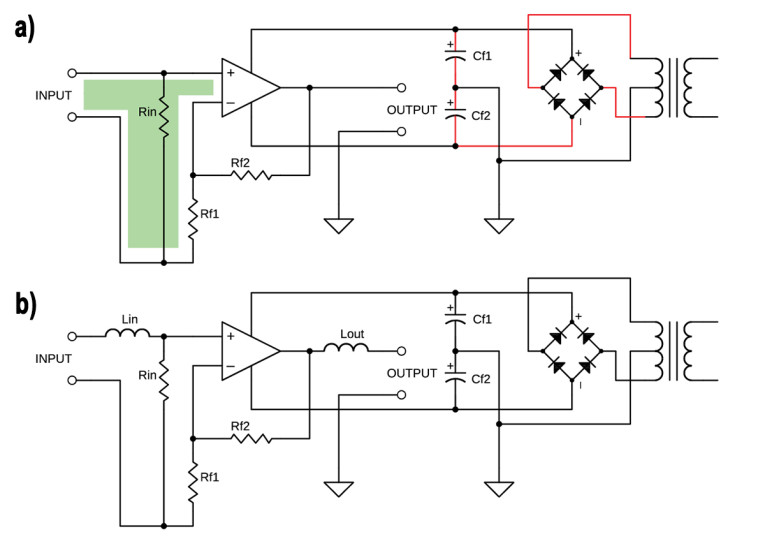
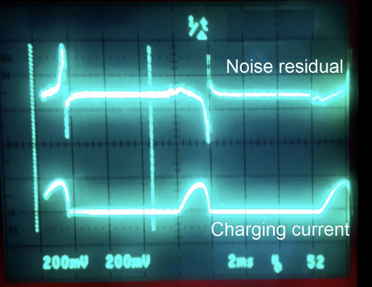
In conventional audio amplifiers, significant alternating current flows through the secondary winding of the power transformer, the rectifier (bridge), and the main reservoir capacitors Cf1 and Cf2. This current path is marked with red in Figure 1a. The typical waveform of the charging current is shown in Figure 2. The charging current can easily reach several dozen Amperes. It generates a large magnetic field, which couple with other amplifier circuits.
The magnetic field is proportional to the current and the cross-sectional area of the loop. Amplifier designers try to minimize the area by twisting wires, keeping the current path short, moving high current conductors away from the amplifier’s front end, shielding, and so forth. The current with the wave form shown in Figure 2 also travels through the transformer primary winding and mains wiring (scaled by the transformer turns ratio).
In audio amplifiers, the input circuit is particularly vulnerable to magnetic fields. This area is marked with green in Figure 1a. The front stage, input terminals (signal source), the feedback resistor, and more form a single turn inductor. The magnetic field from the charging current intersects this single turn inductor and causes a current to flow. This loop current produces a voltage drop, which appears in series with the input signal. While the magnetic field from charging current is minimized by design, there still can be some unwanted residual, induced by this current.
A typical waveform of the unwanted signal on the loudspeaker terminals is shown in Figure 2. Inductive reactance is directly proportional to the frequency and the noise residual waveform has the shape of the rate of change of charging current with time. While the residual level is often less than 1 mV, it is rich with high-order harmonics of mains frequency and can be heard from the midrange driver as an annoying buzz. This is especially true for older amplifiers built with through-hole parts, as it is physically impossible to keep the input loop area small.
The practical solution to reduce buzz in that case is to use a compensation coil, which will inject a nearly equal interference signal with opposite polarity in the signal path. This will cause some degree of buzz compensation in the output signal. Two possible places for the compensation coil are shown in Figure 1b. The compensation coil can be inserted in series with the loudspeaker or in series with signal source.
Experimenting with Potential Solutions
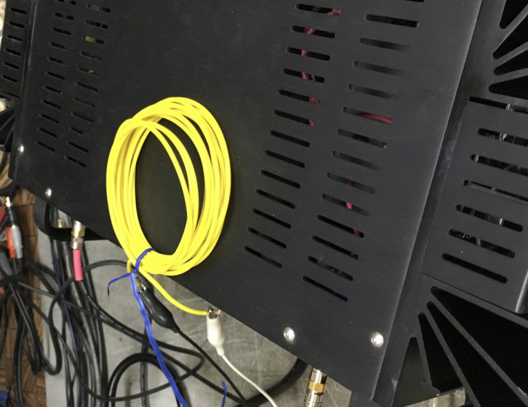
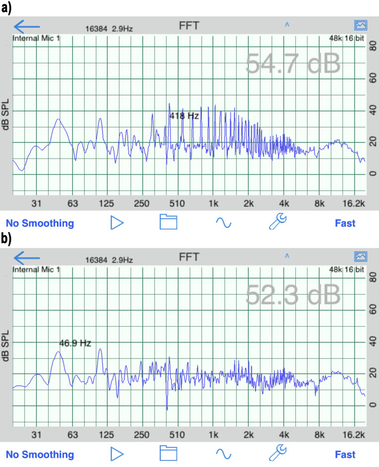
The first experiment was done with the output coil, shown in Photo 1. The yellow coiled wire is inserted between the speaker wire and the output binding post. The number of turns and orientation of the coil was adjusted for best sonic results. Spectrums of the residual without output compensation coil and with it are shown in Figure 3. The result is a very audible reduction in the buzz. Most of the harmonics are down 10 dB to 20 dB. As expected turning the coil over increases the buzz two times. Ten turns of wire is a good starting point.
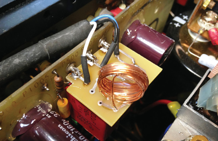
The second experiment was done with the input coil, shown in Photo 2. The number of turns and orientation of the coil was adjusted until the best results were achieved. The final coil has 15 turns of magnet wire, wound on a 0.5” former. Coil turns are bonded together with hot melt adhesive. The coil is shunted with a 49.9 Ω CMF55 resistor. The coil was rotated and bent in three dimensions until the best results were achieved.
The buzz spectrums with and without an input compensation coil are shown in Figure 4. Again, there is solid improvement. It looks like while it attenuates the odd harmonics, the even harmonics are boosted, maybe because the input coil is physically located between several conductors with currents.

When implementing this technique, it is recommended to monitor the noise residual on the speaker terminals with the sensitive scope or by using a spectrum analyzer. It will provide help to find the right orientation of a compensation coil, the coil diameter, and the number of turns.
Resource
H. W. Ott, Noise Reduction Techniques in Electronic Systems, 2nd Editon, Wiley-Interscience, New York, 1988.
About the Authors
Chris Lewis started Pyramid Audio Service in 1980 after receiving his BSEE from Texas A&M University in 1978. Located in Austin since 1989, Pyramid Audio is the regional warranty station for McIntosh, B&O, Denon, Marantz, Hegel, Yamaha, and Harman luxury audio. Chris has published more than 130 reviews and articles for various magazines including AutoSound & Security, Autosound 2000, and Car Audio & Electronics. He is a home and car audio fanatic and a specialist in 1970 and newer vintage home audio.
Dimitri Danyuk has been the principal hardware engineer at Harman luxury audio since 2013. He was graduated with honors from Kyiv Polytehnic in 1985. His passion is to help audiophiles in all aspects of audio design. His articles have appeared in a number of magazines including the Journal of the Audio Engineering Society, IEEE Transactions, EDN, Electronic Design, etc. Dimitri also provides consulting services for various businesses.
This article was originally published in audioXpress, July 2019.