As I mentioned in my previous explication of the U80W Mundorf AMT, there has been a “renaissance” in AMTs over the last several years, and we now find AMTs used not only by home audio companies such as MartinLogan, Gryphon, Elac, Wharfedale, Arion, Emotiva, and Burmester Audio (which uses the Mundorf AMTs), but also in pro sound, in both studio monitors (Adam, Presonus, HEDD, and Eve Audio) and AMT drivers for PA applications, such as the Beyma TPL-200/H or the Eighteen Sound AMT200P (Mundorf also has a pro sound AMT available). The “Concert” AMT is a single monopole model, although there is a similar dipole variant, the AMT 23D6.1-C
The diaphragm material used in all the Mundorf AMTs is a proprietary blend, as explained by Mundorf: “All of our AMT diaphragms are manufactured in-house by a unique manufacturing process of our own development. The mixture of our basic diaphragm material was optimized with focus on its acoustic properties, hereafter the manufacturing process was tailored to ensure the very best acoustical result possible with every single diaphragm material mix. Every detail of our diaphragm‘s geometry is based on a deep understanding of the mechanical requirements and physical properties of an AMT diaphragm. Only with this knowledge is it possible to achieve the perfect ratio of a low diaphragm weight, the highest possible diaphragm flexibility, and the most effective inner damping at a maximum of diaphragm stability. Even the slightest shift within this well-balanced ratio would lead to audibly worse results. This out-balanced ratio makes the Mundorf AMT diaphragm one of its kind. Due to its exceptionally high inner damping, it is characterized by extremely low distortion data. This applies particularly to the odd-numbered harmonic distortions K3 and K5.”
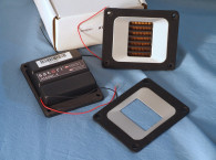
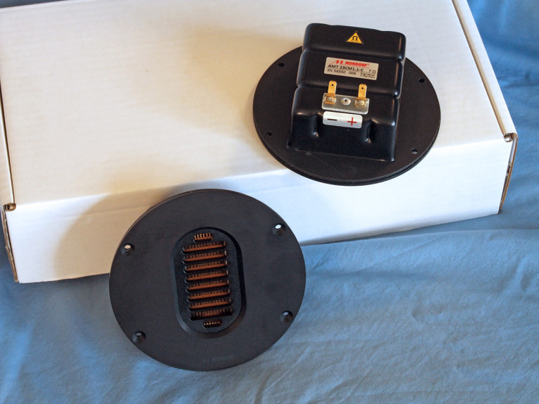
Features for the Mundorf AMT 23CM1.1-C, shown in Photo 1 and Photo 2, include a 130mm × 53mm pleated proprietary AMT diaphragm, an optimized injection-molded rear chamber, a flat round metal face plate, 90dB sensitivity, 125W power handling with a minimum second-order 2.2kHz high-pass network (2.7kHz first-order network), gold-plated solderable terminals, and a diaphragm area (Sd) of 68.9cm2.
Testing commenced using the LinearX LMS analyzer to produce the 300-point stepped sine wave impedance plot shown in Figure 1. With a nominal 7Ω impedance, the Mundorf Concert AMT 23CM1.1-C has a 6.44Ω DCR, with minimum impedance of 6.49Ω and at 1kHz, which is not particularly significant since the amount of reactance in this type of transducer is minimal. Mundorf does not specify a resonance frequency for the AMT 23CM1.1-C, which is appropriate and as can be seen, there really is no discernable resonance to this AMT transducer.
For the next set of SPL measurements, I recess mounted the AMT 23CM1.1-C in an enclosure that had a 15” × 6.5” baffle area and measured both the horizontal and vertical on- and off-axis at 2.0V/0.5m (normalized to 2.83V/1m) from 0° on-axis to 45° off-axis using the Loudsoft FINE R+D analyzer and GRAS 46BE microphone (again, supplied courtesy of Loudsoft and GRAS Sound & Vibration). Due the asymmetrical diaphragm shape, AMTs have a vertical directivity that is significant enough to be taken into account, which is why I also performed a series of vertical plane as well as horizontal plane measurements.
Figure 2 displays the on-axis frequency response of the AMT 23CM1.1-C. The response is ±1.97dB with no major anomalies from 2kHz to 20kHz, and a usable response out to about 40kHz, beginning its second-order low-pass roll-off at above 40kHz. Figure 3 shows the 0° to 45° on- and off-axis response in the horizontal plane. Figure 4 displays the normalized horizontal plane response. Figure 5 shows the 180° horizontal polar plot (in 10° increments with 1/3 octave smoothing applied), generated by the CLIO Pocket analyzer and the accompanying microphone (courtesy of Audiomatica SRL).
For the vertical plane, Figure 6 gives the 0° to 45° response, normalized in Figure 7. Figure 8 shows the CLIO-generated polar plot. Last, Figure 9 provides the two-sample SPL comparison, showing the two Mundorf AMT 23CM1.1-C driver samples to be matched within 1dB or less throughout the entire operating range of the transducer.
For the remaining series of tests, I set up the Listen, Inc. AudioConnect analyzer and 1/4” SCM microphone (provided to Voice Coil by Listen, Inc.) to measure distortion and generate time-frequency plots. For the distortion measurement, I again mounted the AMT 23CM1.1-C in the same enclosure as was used for the frequency response measurements. I then set the SPL to 94dB at 1m (3.89V determined by using a pink noise stimulus generator and internal SLM in the SoundCheck 18 software). Next, I measured the distortion with the Listen microphone placed 10cm from the mouth of the AMT diaphragm. This produced the distortion curves shown in Figure 10. Note the extremely low third-harmonic level.
Following this test sequence, I then set up SoundCheck to generate a 2.83V/1m impulse response curve for the AMT 23CM1.1-C and imported the data into Listen’s SoundMap Time/Frequency software. Figure 11 shows the resulting cumulative spectral decay (CSD) waterfall plot. Figure 12 shows the Short Time Fourier Transform (STFT) plot.
After examining the data, I found that the Mundorf-designed AMT 23CM1.1-C, as with last month’s Mundorf U80W AMT, definitely exhibits excellent performance, which is what you would expect from a respected high-end home audio manufacturer such as Mundorf. For more information about the AMT 23CM1.1-C and other Mundorf products, visit
www.mundorf.com VC
This article was originally published in Voice Coil, April 2022.