SonicEdge developed a unique speaker based on a MEMS technology that generates sound in a new way. The company was founded in Israel in 2019 and has expanded rapidly worldwide. SonicEdge’s office in Denmark has been part of the Sound Hub Denmark and Danish Sound Cluster since 2021. The SonicEdge speakers utilize active ultrasound modulation [1], providing enhanced audio at low frequencies and extended operation up to 20kHz and beyond. These speakers are smaller in size, produce no vibrations, have a reduced back cavity, are easy to use and integrate, and can be manufactured with high uniformity, similar to semiconductors. SonicEdge’s initial focus is on the $80 billion USD true wireless stereo (TWS) market, where their speakers enable smaller, more comfortable, and better sounding earphones.
Transducer Principle
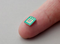
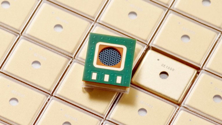
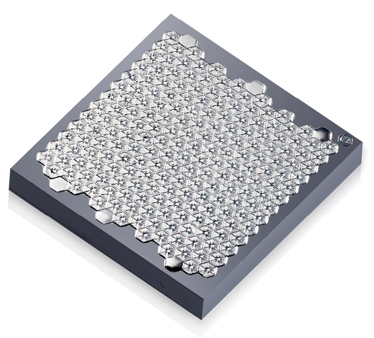
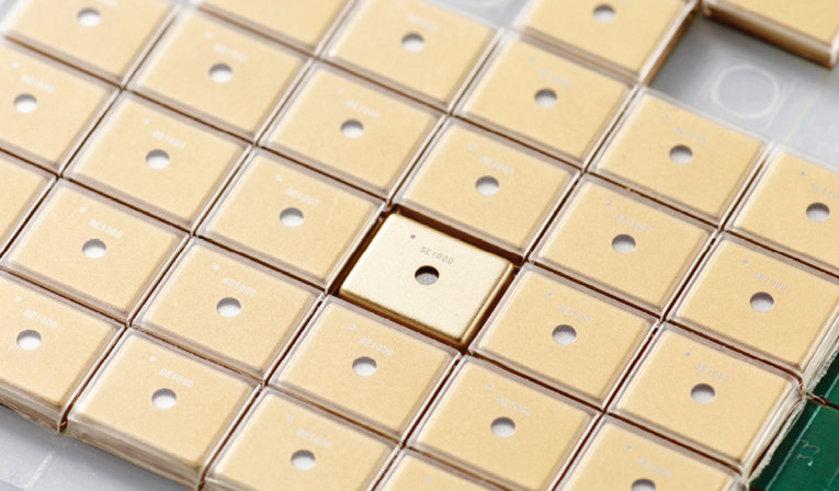
The SonicEdge transducer is based on actively modulated ultrasound to produce sound. Several key points set this transducer apart from other types, such as electrodynamic transducers or balanced armature receivers [2]. SonicEdge’s first product is the SE1000. It has 200 modulated ultrasound transducers, each composed of an ultrasound speaker and an acoustic modulator. The total driver active area is 10mm2. Photo 1 shows the MEMS chip and the packaged device. The individual transducer cross-section is shown in Photo 2.
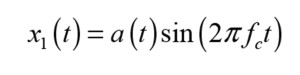
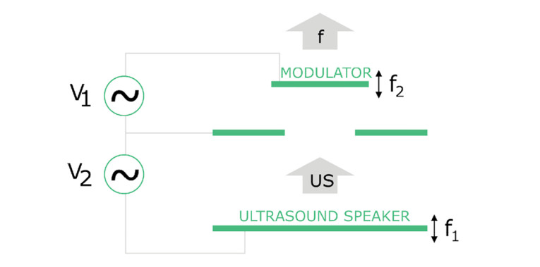
The structure is composed of three membranes. The bottom membrane is called an ultrasound speaker and the top membrane is called a demodulator. Both membranes are driven electrostatically, with the middle membrane functioning as a ground. In Figure 1, f1 and f2 represent the vibration frequencies. The bottom membrane is excited via a signal, which is the multiplication of an acoustic signal a(t) and a carrier signal sin(2πfct):
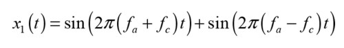
This results in a so-called Dual Band Modulation, resulting in two sidebands around the carrier frequency. If we illustrate this with a simple sinusoidal acoustic signal, the result is the sum of two signals—one having frequency content at the sum of the carrier frequency and the acoustical frequency, and the other having the difference frequency:
Note that both components are at ultrasound frequencies, which generally holds for any relevant acoustical signal. The top membrane is actuated to vibrate, and its vibration defines the channel cross-section between the top and middle membrane. As a result, the movement of the top membrane changes the acoustic impedance of the ultrasound signal, so the resulting signal is amplitude modulation (AM) of the ultrasound signal. The modulator acoustic action is given by:
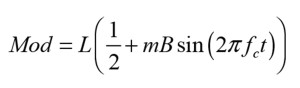
L and m can be found from the acoustic loss imposed by the modulator on the acoustic beam in the open and closed position of the modulator.
The final output from the single cell is proportional to the sum of the carrier signal and the modulated air channel as in:
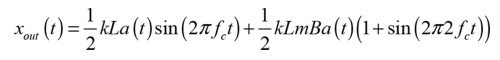
Here, the audio output can be recognized in the middle part of the equation. Whereas ultrasonic output is present in addition to the audio output, the carrier frequency is at hundreds of kilohertz, and the presence of ultrasonic energy does not cause any health issues to humans, even with long-term exposure [3].
It may seem like a roundabout way to generate the acoustic output compared to simply applying the audio signal to a single membrane. But the unique setup with modulated ultrasound comes with several advantages:
- The only “part” moving at acoustic frequencies is the air, hence no mechanical vibrations, and there is no need to address mechanical vibration considerations in earphone or hearing aid design.
- The transducer is essentially a constant flow generator and will be unaffected by external acoustic loads.
- The transducer is modeled as a constant “current” source or constant volume velocity in the acoustic domain when using lumped or finite element modeling.
- Size reduction results from the understanding that SonicEdge’s speaker replaces the membrane in standard speakers with a pump operating at hundreds of kilohertz, pushing air more effectively and requiring 10 times less area and 10 times less displacement.
Modeling of SonicEdge Speaker
A standard electrodynamic speaker can be described by a two-way Lorentz force coupling between the voice coil (electromagnetic) and the moving parts (structural mechanics). The mechanical setup is that of a spring-mass system with an associated fundamental frequency. Above this fundamental frequency, the behavior is mass-controlled with a resulting flat acceleration response, whereas below the fundamental frequency, the behavior is stiffness controlled with a flat displacement response.
For applications where the loudspeaker is playing in a “free field,” the resulting sound pressure level will be flat above the fundamental frequency but will not produce much sound below it. Also, the transducer is affected by the said acoustic environment. For example, a rear volume behind it will increase the fundamental frequency. To model a resulting sound pressure, one must account for the two-way coupling between structural mechanics and acoustics.
The SonicEdge transducer is fundamentally different and can be modeled more simply with a current source. Since there is no internal impedance in this model, the acoustic impedance will not affect the volume velocity, which has been validated by measurements. The volume velocity, as well as the acoustic pressure downstream, will depend on the acoustic environment, but the audio design work will be quite different with this transducer, as it has no distinct fundamental frequency as opposed to other transducers that have a spring-mass type mechanical setup internally.
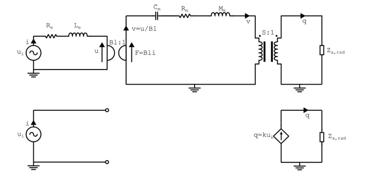
In a previous article [2], we looked at the modeling of an electrodynamic speaker driver and a Balanced Armature Receiver. In Figure 2, we compare the lumped element description of a SonicEdge transducer to a standard electrodynamic driver.
Examples
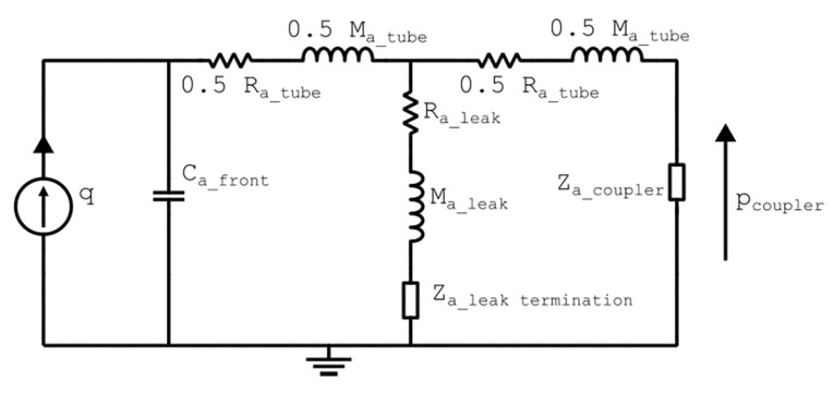
Two modeling approaches are demonstrated and compared for the SonicEdge transducer using the lumped and the finite modeling, respectively. Both models include the transducer as a volume velocity (or current) source. Features such as vent and leakage ports are introduced in the acoustic path to shape the sound pressure level frequency response.
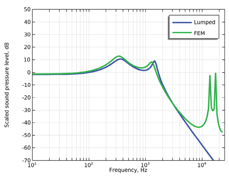
Specifically, the transducer plays into a front volume and connects to a larger coupler volume via a tube with a leak whose radius and length can be varied to tune the acoustic pressure in the coupler. The lumped element model for this setup is shown in Figure 3, and the responses from the two modeling approaches are compared in Figure 4. Good agreement can be seen up to 10kHz, where the lumped element assumption is challenged.
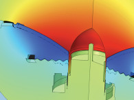
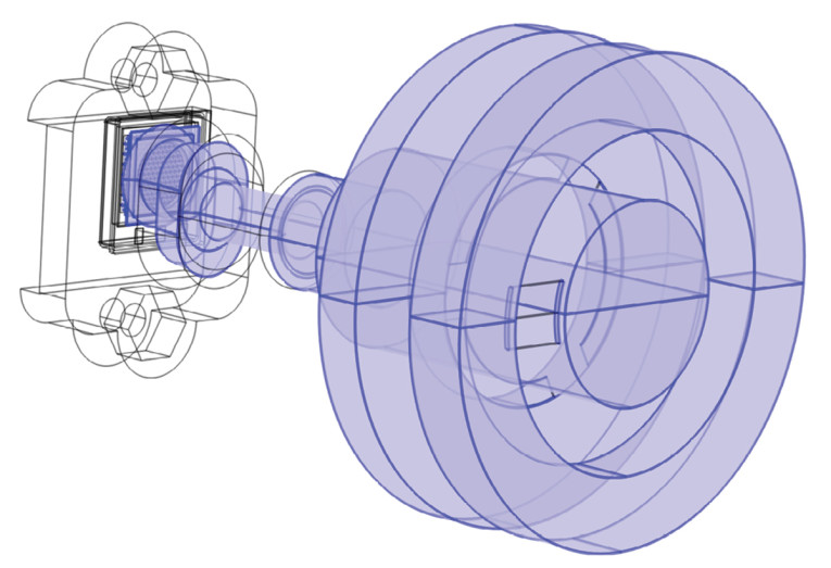
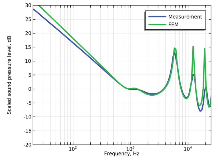
Going toward a more realistic geometry, the SE1000 was placed in a housing and attached to a 711 Coupler, described in the international standard IEC 60318-4, as shown in Figure 5, where the SE1000 geometry is explicitly included, and each single cell has an associated velocity boundary condition. For these more complex geometries, it can be challenging to set up accurate lumped models, and so by using simulation software such as COMSOL Multiphysics, different housing configurations can be tried out quickly and efficiently. With the focus here being on the placement of the first resonance, the finite element can take into account acoustic losses in a simplified manner as the peak height is of less interest in the initial investigations, with the measured and simulated sound pressure levels shown in Figure 6.
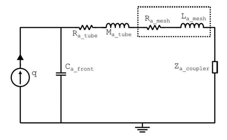
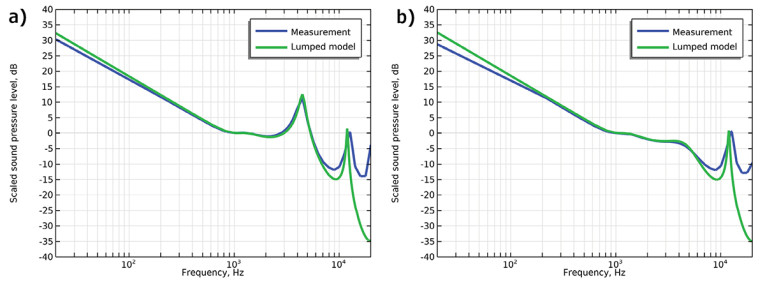
In the following example, a mesh from SAATI’s Acoustex product range with a specific airflow resistance of 160 MKS rayls is mounted at the end of the housing tube. The lumped circuit in Figure 7 illustrates this situation and compared to measurements in Figure 8, with and without the mesh included.
Conclusion
The novel SonicEdge transducer can deliver constant volume velocity across audio frequencies and beyond. This transducer differs from other available transducers in that it can be modeled simply as a constant volume velocity source, an “audio-pump” with negligible vibrations, alleviating certain noise-cancellation and feedback application challenges. Together with Acculution, SonicEdge demonstrated how to model the transducer in lumped-element and finite-element acoustic simulations and how to tailor a desired SPL response using acoustic features. aX
References
[1] M. Margalit, “Techniques for Generating Audio Signals, Patent US8861752, October 14, 2014.
[2] R. Christensen, “Lumped Element Modeling of Transducers,” audioXpress, March 2023.
[3] Health Protection Agency, “Health Effects of Exposure to Ultrasound and Infrasound,” 2010.
This article was originally published in audioXpress, August 2023