Simulation software gives insight into physical products that could not be achieved otherwise. You can get the stress in any point in a vibrating structure, and the resulting acoustic pressure at any desired point and angle. So, it would be natural to think that less and less attention is paid to analytical methods where some descriptive mathematical expression related to the physical application can be found. While this may be the case for some simulation engineers using the software as more of a black box tool for trial-and-error runs, the real power of simulations comes from understanding not only the underlying numerical methods, but also alternative approaches used before simulations were an option.
The are at least two aspects to consider here. One is that alternative methods can provide validation cases to make sure that the simulation is ballpark correct, while the simulation itself rarely has any way of expressing its own correctness. The other relates to simplifying the simulation model by combining it with some analytical setup to form hybrid models that will solve faster and on standard computers while approximating the same results. In this article, and some of the upcoming ones, we will explore some analytical approximation methods, starting here with perturbation methods.
Perturbation Methods
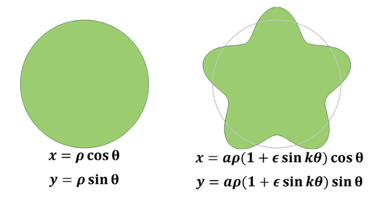
Imagine that you know the solution to a problem analytically and exactly for a particular geometry, for example the sound field in a tube with a circular cross-section. Now, if you instead considered some arbitrary geometry that does not resemble a circle, you might still be able to estimate the results based on comparing cross-sectional areas. However, if the new geometry can somehow be described as a “perturbed” version of the original, a perturbation approach may give an analytical expression that approximates the exact result for deformed geometry based on the original geometry and its corresponding solution. An example is taken from the viscous flow literature [1], where an exact solution for a parameter α characterizing the viscous loss in a tube is known to be 8π for the circular cross-section. Three perturbations parameters define a scaling factor and an overall deformation or “shape perturbation” that gives k indents in the original geometry of a depth related to the parameter ε, see Figure 1. The resulting α can then be found as a function of an integer k>2 as:

where the so-called compactness factor C(k,ε) is the ratio between perimeter squared and the area and this can be calculated analytically also, in this case as:
It is thus a matter of simple insertion to calculate how much the viscous loss is increased when some shape perturbation is applied to the original circular geometry, without a numerical simulation for each geometry of interest. This approximative solution may start to fail when the deviations from the circular geometry are large, and so numerical methods may be needed.
For the example shown in Figure 1, the compactness factor is calculated as:

and so, the characteristic factor α is:

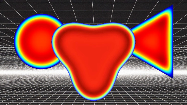
This is 32% higher than the 8π for the circular, so the viscous losses have increased as expected, since the perimeter is larger in the deformed case. I found via a numerical calculation of the viscous losses (see Figure 2), that the deformed geometry has 31% higher losses, so the perturbation method gives very accurate results for this deformation. In a similar manner, one could probably find the characteristic factor α for a perturbed equilateral triangle, or any other shape for which an analytical solution exists and where sensible perturbation parameters describe a desired deformation. It may be a difficult task to arrive at the mathematical setup, but if the results are to be found for many deformation variations, it may be well worth it in principle.
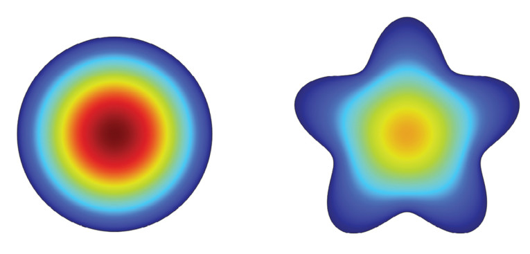
An example of a geometry perturbation is given in Figure 3, where a 2D geometry represents a cross-section of the room, with the full 3D geometry given by an extrusion. Thus, one length dimension stays the same for any perturbation. Deforming the room like this will generally change the modes, but if it is done in a way that has a mathematical description and it is not too extreme, the perturbation method will give the modes related to the deformed room in an analytical form.
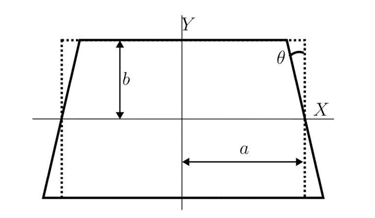
The modal frequencies for the symmetric setup in Figure 3 are given as:

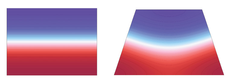
with f0n as the corresponding modal frequency for the unperturbed rectangular room, and the summation excluding any singular values (k ≠ n). Further details can be found in the R. H. Bolt, H. Feshbach, and A. M. Clogston article [2]. At least it can be noted that modal frequencies will be influenced by the skewness of the trapezoid as expected, but this is still an approximation based on some assumptions regarding how large the deformation is. In a similar manner, the actual pressure distribution for each mode is also given analytically, and so they can be plotted also. As already mentioned, the analytical expressions are quite complicated, but it would seem from a quick implementation that the modal behavior is indeed captured, as seen in Figure 4.
Other deformations, such as parallelogram-shaped cross-sections, can also be handled analytically, and it would be interesting to see if, for example, the sinusoidal deformation in Figure 1 or a semicircular deformation of the sidewalls can also be expressed analytically. With the original paper being from 1942, it is clearly from a time when running a finite element method simulation was not an option, and so the relevance today is arguably lower. However, working with these examples will prepare you for situations, where an analytical approach is the perfect way to go.
Conformal Mapping
The described perturbation method may look like a different approach called Conformal Mapping. Conformal Mapping can be useful when some deformed geometry can be mapped to a simpler geometry for which an analytical solution is more easily established, and have that solution mapped back onto the original geometry. It is illustrated here for static potential problem [3] with a starting geometry with two non-coaxial cylinders where the boundary potentials (Dirichlet boundary conditions) are known, as shown in Figure 5. The initial geometry is shown in z-plane (x,y), where the “parent” element we wish to map to is in the w-plane (u,v), see the general topic of Complex Analysis for more details.
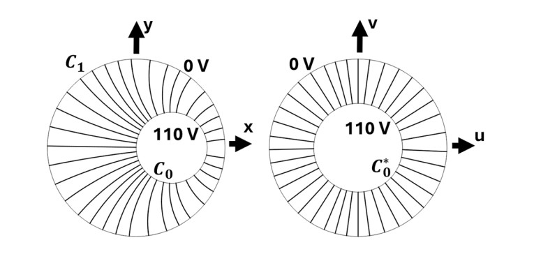

such that each point in the z-plane has a unique counterpart in the w-plane. So, it is required that the mapping can be written in some mathematical form that suits the purpose here. Then, in the w-plane the solution can be found as a standard potential problem to give:
and this can then be mapped to the original deformed geometry as:

The resulting fields, now known analytically are illustrated in both z-plane and w-plane in Figure 6, without any need for a numerical analysis. With this technique, the effect of a deformation on an ideal geometry can be assessed analytically for certain types of problems, as an alternative to the approximative perturbation technique.
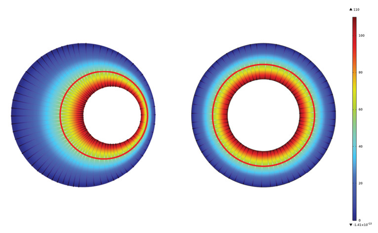
Note the difference between knowing an analytical mapping to more well-behaved problem and back-mapping of the solution for the conformal mapping, and then the modification of an analytical solution for a simpler geometry via a known deformation for the perturbation method. Each method comes with approximations and limitations.
Closing Comments
With enough foundational knowledge, solutions can fall out almost as a byproduct of constant focused research, looking at both classical techniques and new developments. It is not always a good idea to jump straight for the simulation software, as it will typically bring a layer of detachment compared to having worked out an analytical solution, even when the latter is only an approximation. There are always some unique insights to be had in the process of manipulating mathematical expressions, and parameter and sensitivity studies run much faster with analytical solutions. In some upcoming articles, we will show new work in microacoustics that is the direct result of purely analytical work, bringing novel accurate analogy circuits to the acoustical engineering community. aX
References
[1] N. A. Mortensen, F. Okkels, and H. Bruus, “Reexamination of Hagen-Poiseuille flow: shape dependency of the hydraulic resistance in microchannels,” Physical Review E, Volume 71, 2005.
[2] R. H. Bolt, H. Feshback, and A. M. Clogston, “Perturbation of sound waves in irregular rooms,” Journal of the Acoustical Society of America, pp. 65-73, 1942.
[3] E. Kreyszig, Advanced Engineering Methods, John Wiley & Sons, Inc., 1993.
This article was originally published in audioXpress, January 2025


