The first step was to produce non-engineered TPCDs with uniform thickness and stiffness, or in other words how conventional diaphragms are made. These non-engineered TPCD diaphragms showed benefits over the current diaphragms — the resonances (break up) were moved to higher frequencies and their amplitudes were reduced. But the resonances were still there.
In the second step, we produced engineered TPCD diaphragms, for which thickness and stiffness had been optimized in different areas of the diaphragms. The results of the engineered TPCDs were game-changing. The problematic resonances were not just moved; they were eliminated. The distortion peaks found in the drivers with the current diaphragms vanished.
For years we had been envisioning adapting the TPCD technology for over-ear headphone diaphragms. This research project showed us we could do it and that it had the potential to make a real difference. The moral of this story is that although TPCD is a great speaker diaphragm material, it is a game-changing speaker diaphragm technology. It is Composite Sound’s diaphragm engineering that makes the difference.
Undesired Resonances - An Enemy of Good Sound Quality
In Sound Reproduction — The Acoustics and Psychoacoustics of Loudspeakers and Rooms by Floyd Toole, an objective for loudspeaker performance is described as timbral neutrality. In other words, the loudspeaker or headphone should not add or subtract from the sound it is to reproduce. Furthermore, Toole says the biggest culprits in coloration are resonances, and “by reducing the amplitude, the audibility of the resonance is reduced, as is the ringing.”
Resonances show up as peaks and dips in the frequency response curve. A bumpy frequency curve with sharp peaks and dips is therefore a strong indicator of a poorly sounding loudspeaker or headphone. However, a smooth and flat frequency response curve that extends over the entire audible frequency range is an indicator of a good sounding, or at least neutral, loudspeaker or headphone.
Most high-end loudspeaker systems have the luxury of using multiple drivers and diaphragms, each covering a limited frequency range. Headphones typically use one driver and diaphragm that should ideally cover the entire audible frequency range. Having the diaphragm operate without undesired resonances in this full-range bandwidth is more challenging in a headphone. That also means that the ability to control diaphragm resonances in headphones could potentially make an even bigger difference than in a loudspeaker two- or three-way system.
The Conventional Way to Handle Diaphragm Resonances
There are many sources of resonances. In this article, however, only resonances originating from the diaphragm will be discussed.
It is usually said that the ideal diaphragm should be stiff, of low density, and well damped. High stiffness to density will move resonances (break up) higher up in frequency. Damping will reduce the amplitude of the resonances as well as their ringing.
Producing an ideal diaphragm in the conventional way means using a diaphragm material with high stiffness, low density, and high loss factor (well damped). The problem is that such a material doesn’t exist — a stiff material is usually poorly damped and with a high density. A well damped material usually has a low stiffness. This forces the designer to make a choice as far as what to sacrifice.
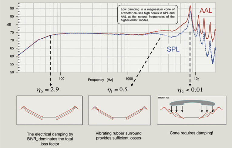
There are conventionally two opposite ways to handle this, each with its own set of sacrifices. The first is the “hard diaphragm way,” using as stiff a diaphragm material as possible to move resonances far enough in frequency so they are not in the audible range. The downside is that the stiffer the material, the less damped it tends to be, meaning that break up when it arrives is severe, producing audible artifacts (Figure 1).
The other way is to accept that there are resonances in the audible range but using damping in the diaphragm to reduce the amplitude, ringing, and thereby the effects of the resonances. Using a more damped material also usually means using a less stiff material, resulting in resonances appearing at lower frequencies.
Producing a conventional diaphragm, whether it’s for a loudspeaker or a headphone, is typically done by forming a sheet of material. If the sheet has a uniform thickness, the diaphragm will have a uniform thickness, which is highly sub-optimized, at least if the target is a stiff, low-mass diaphragm with controlled resonances. But, is there a way to reduce the effects of undesired resonances without the drawbacks associated with the conventional ways described above?
What happens if we take a different approach: instead of merely trying to reduce the negative effects of undesired resonances (break-up), we control what is causing them?
Composite Sound — Born from F1 and Space
Composite Sound is not about standard diaphragms. In fact, Composite Sound doesn’t have any off-the-shelf diaphragms. However, if you are looking for a diaphragm solution that is tailored to your specific requirements and visions, and a diaphragm that makes a true difference in your headphones or loudspeakers, then we have common ground.
To us an ideal diaphragm relieves you from having to make compromises. An ideal diaphragm enables you to make it sound like you want it to sound. An ideal diaphragm enables you to realize your visions. Engineering an ideal TPCD diaphragm is what Composite Sound is all about. We do things differently because we come from a different background.
Based in Borås, Sweden, Composite Sound is a spin-off from Oxeon, the inventors and producers of TeXtreme thin-ply carbon materials. TeXtreme is used in applications with the absolute highest requirements on stiffness, low mass and durability. TeXtreme is used when other materials, including conventional carbon fiber, are not stiff enough, not light enough, or not durable enough. TeXtreme helps Formula One (F1) race cars run faster, and has enabled NASA to explore Mars. NASA’s drone Ingenuity is largely built from TeXtreme thin-ply carbon material (Photo 1).

Although high-performance thin-ply carbon composites have great material properties, what makes it truly different from conventional technology is its engineering. Thin-ply carbon composite technology provides freedom of engineering properties in different areas and directions to maximize stiffness, minimize mass, and even enable the composite part to behave in certain desired ways under certain conditions. That is what Composite Sound uses to engineer loudspeaker diaphragms and what we are now introducing to over-ear headphones.
Engineering TPCD for Headphones
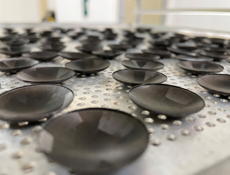
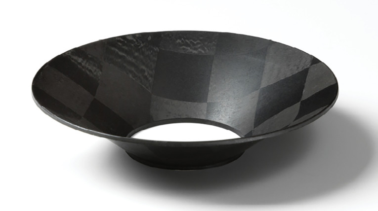
Just as we did in in the research project described at the beginning of this article, engineering a TPCD headphone diaphragm is about combining the resonance control abilities of Composite Sound’s bigger cones with the thinness, stiffness, and lightness of our tweeter domes (Photo 2 and Photo 3). Composite Sound’s production process is scalable, meaning the same principles and processes that enable an optimized 110mm midrange cone with 0.2mm thickness can also be used for a 30mm over-ear headphone diaphragm with 0.05mm thickness.
To Composite Sound, an ideal diaphragm is stiff, of low mass and doesn’t suffer from undesired resonances. The most basic way of engineering a diaphragm with these objectives is to optimize the thickness in different areas of the diaphragm. Strangely enough, it is hardly ever used in conventional diaphragms.
Stiffness and Mass
Imagine you want to build a bridge. Your goal is to build a bridge with a large span crossing wide waters. The requirements are tough: the bridge must handle cars and trucks, heavy winds, and even withstand earthquakes and ships crashing into it. To up the challenge, it should use as little material as possible. How would you build it? Would you use a uniform sheet of steel or concrete and build the bridge equally thick in all places?
A headphone diaphragm has more similarities to a bridge than you might first think. Just as the bridge can be made a hundred times longer with an optimized thickness and stiffness profile, combining tension and compression, the TPCD headphone diaphragm can also be tailored to perform at a substantially higher level than current diaphragm technology.
Let’s look at an example comparing three 30mm diaphragms for a 40mm over-ear headphone driver with the same geometry and mass, weighing 0.06 grams. Diaphragm A is made from 30µm thick aluminum. Diaphragm B is a non-engineered TPCD with uniform thickness. Due to the 40% lower density, it will have a 40% higher thickness than the aluminum diaphragm, 50µm. Diaphragm C is a TPCD with 40µm thickness but with double
thickness just around the area where the voice coil is attached (Figure 2).
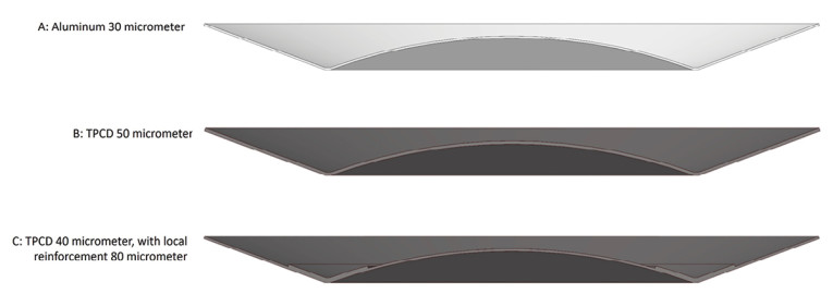
Using simulations in ANSYS with simplified boundary conditions of the diaphragm in isolation, the resulting fundamental resonances (break-up) occurs at the following frequencies:
- Diaphragm A, aluminum: 7.5kHz
- Diaphragm B, uniform thickness TPCD: 12.4kHz
- Diaphragm C, varying thickness TPCD: 16.1kHz
The only engineering that has been made to Diaphragm C is doubling the thickness of an important part of the diaphragm. There is much more that can be optimized in this diaphragm.
What possibilities does this provide? To name a few:
- The diaphragm can be made bigger for better bass performance.
- Resonances can be controlled for better sound quality.
- Mass can be reduced for higher sensitivity.
- The level of optimization can be taken much further.
- Controlling Resonances
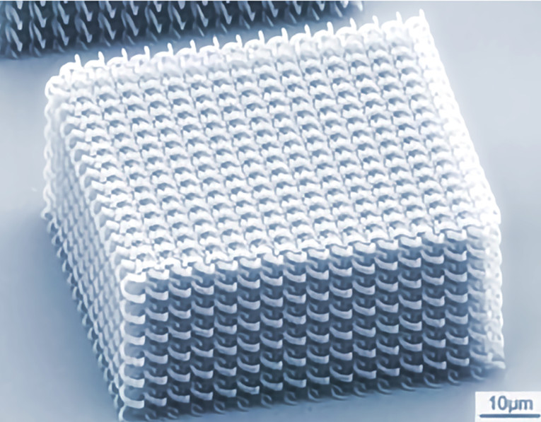
A metamaterial is organized into a structure to give it a behavior or performance that is not naturally occurring in the material itself. In the same way that metamaterials can be artificially structured to control light and metasurfaces to manipulate soundwaves, Composite Sound Metamodal technology can control and manipulate resonances.
An example of metamaterial structure and a Composite Sound TPCD metamodal diaphragm share a common approach, in that its properties can be engineered to fit the application target (Photo 4 and Photo 5).
This may sound like magic, but it is physics. Any time the thickness, stiffness, or density is changed in any location of an object, it will change how resonances occur in that object when excited. Hence, by optimizing these factors, it is possible to control the resonances in that object.
F. J. M. Frankort describes diaphragm resonances in the Audio Engineering Society (AES) paper “Vibration Patterns and Radiation Behavior of Loudspeaker Cones.” [2] The diaphragm is defined as a truncated cone with an inner and outer edge, in which the voice coil is attached to the inner edge. When the voice coil moves, it will create a wave that will travel from the inner to the outer edge of the cone. Although some wave energy will be lost in the diaphragm (in the model Frankort disregards the surround), the wave will be reflected on the outer edge and travel back to the inner edge. If the wave is in phase with the voice coil movement, the amplitude of the wave will be increased, and a resonance is created.
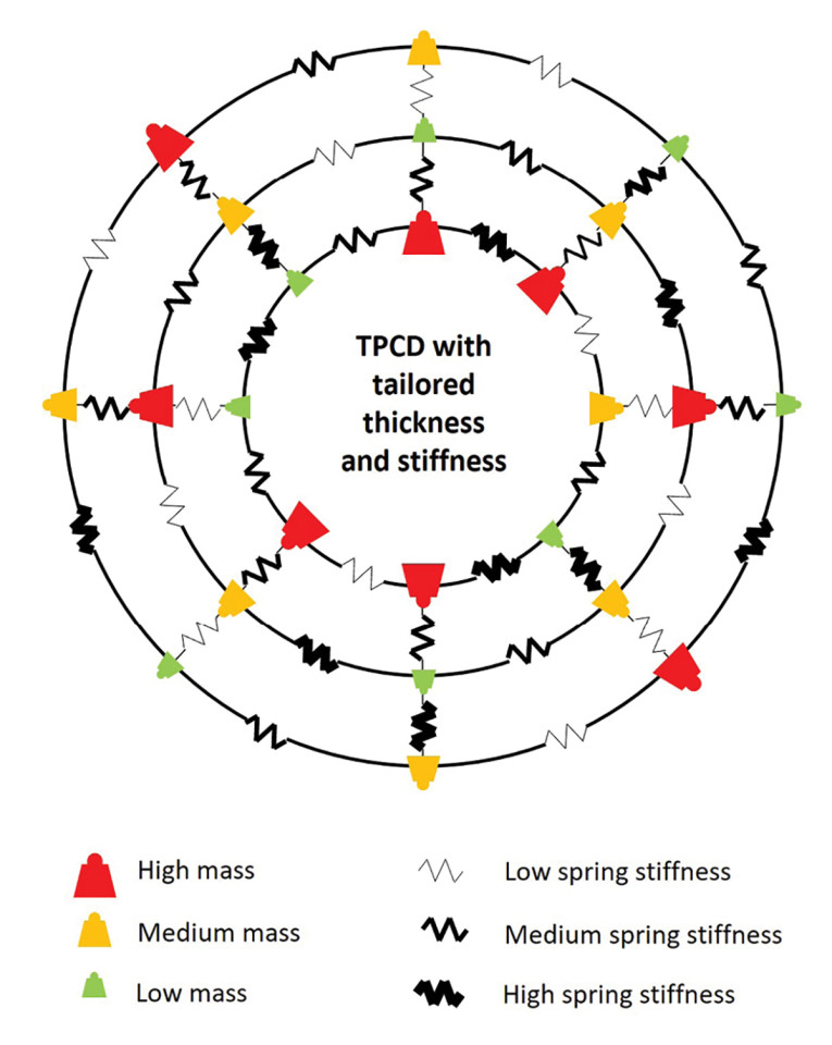
Furthermore, Frankort describes the diaphragm (cone) as a system of masses and springs in the longitudinal direction (from the inner to the outer edge) and as springs in the azimuthal direction (going around the cone). As we go further toward the outer edge, the masses will increase, and the stiffness of the azimuthal springs will decrease (Figure 3).
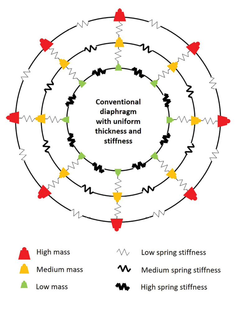
Using a diaphragm with uniform thickness and uniform stiffness, as conventional diaphragms are made, means that the diaphragm will not be able to compensate or adjust for this effect with increased mass and reduced spring stiffness going from the inner to outer edge (Figure 4).
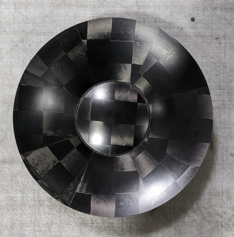
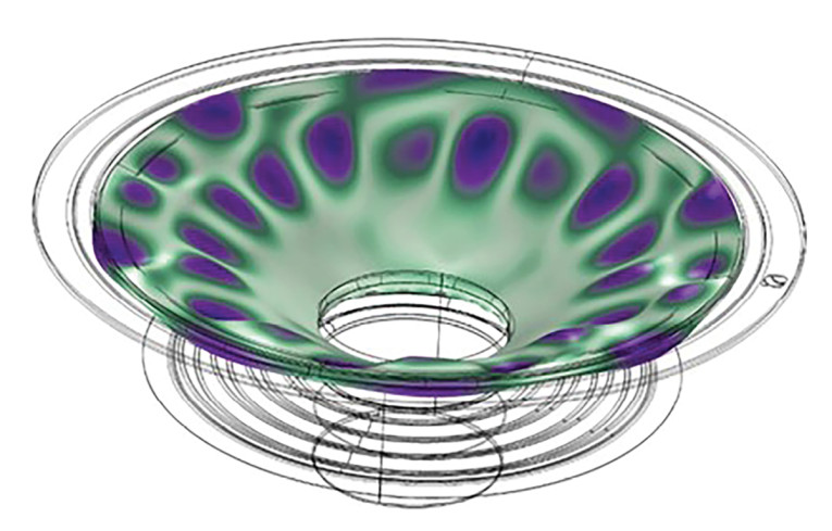
It will also not be possible to adjust for and tailor how resonances occur. Under symmetric conditions the modes will be symmetric meaning large areas of the diaphragm will move in and out of synch at certain resonance frequencies causing big peaks and dips in the frequency response. The waves will arrive at the outer edge around the cone at the same time, in a similar fashion as the ripples from a drop will reach the edge of a bowl of water (Photo 6).

However, if it is possible to change the thickness and stiffness profile of the diaphragm, the mass loads and stiffnesses of the springs can be changed, and thereby the modal behavior and how the resonances occur can be changed.
Frankort’s model covers axisymmetric cones and conditions. This is fine since most conventional diaphragms are isotropic (same properties in all directions) and can be considered axisymmetric.
With Composite Sound’s TPCD Metamodal technology, we can move from 2D axisymmetric conditions to 3D. That means that not only can the thickness and stiffness be tailored going in a longitudinal direction from the inner to the outer edge, but it can also be tailored in different areas and directions as we travel in azimuthal (circumferential direction) around the cone (Figure 5).
A TPCD diaphragm can have one thickness and stiffness profile at 2 o’clock, another at 3 o’clock and yet another at 4 o’clock, etc. In other words, in a TPCD Metamodal diaphragm every mass and every spring in radial and azimuthal direction in any position in the diaphragm can be tailored. If this is done in an ideal manner, it theoretically enables complete ability to control how diaphragm resonances occur.
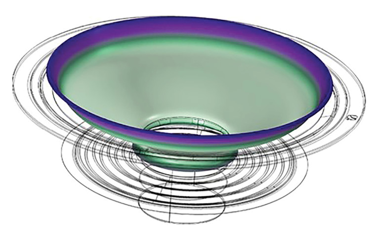
Going back to the analogy with the ripples in the bowl of water, with Composite Sound’s TPCD Metamodal, we can control how the water ripples are formed and travel in the bowl (Figure 6).
The toolbox and possibilities are infinite, our main challenge is to effectively simulate the optimum combination of masses and springs. As those familiar with COMSOL simulations can testify, simulating isotropic materials in 2D is challenging enough, simulating an orthotropic diaphragm (different properties in different directions) in 3D is a massive undertaking.
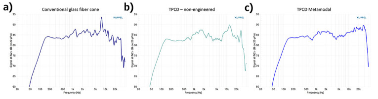
An Example of a Full-Range TPCD Diaphragm
Figure 7 shows frequency curves of the same full-range driver (not a headphone driver), using three different diaphragms of the same geometry and with an outer diameter of 67 mm: Figure 7a shows a conventional glass fiber diaphragm; Figure 7b shows a non-engineered TPCD diaphragm; and Figure 7c is an engineered TPCD Metamodal diaphragm.
Explore, Evaluate, and Realize
To make it easy and transparent to explore, evaluate, and realize engineered and tailored TPCD diaphragms, Composite Sound developed a three-step process:
- Sharing information: The first step is to provide information about the TPCD technology and answer all your questions. It also includes learning about what is important for you and what you are looking for. What would make a real difference for you?
- Pre-study analysis: We perform simulations on the diaphragm/driver you would like to explore with the potential of a Composite Sound TPCD. The simulations will show the potential performance of Composite Sound TPCD compared to your reference diaphragm.
- Prototype testing: Should you wish to test TPCD diaphragms in your headphone, driver, or loudspeaker, we will provide Composite Sound TPCDs tailored for you. Alternatively, we can arrange drivers using Composite Sound TPCD for you to test. Composite Sound cooperates with leading headphone and loudspeaker driver manufacturers.
When you are ready, we will optimize the diaphragms for performance, quality, and manufacturability, and start the production of your tailored Composite Sound TPCDs. aX
References
[1] M. Turesson, “Metamodal TPCDs — Next-Generation Speaker Diaphragms from Composite Sound,” Voice Coil, February 2022, https://audioxpress.com/article/metamodal-tpcds-next-generation-speaker-diaphragms-from-composite-sound
[2] F. J. M. Frankort, “Vibration Patterns and Radiation Behavior of Loudspeaker Cones,” Journal of the Audio Engineering Society (JAES), Volume 26, Issue 9,
pp. 609-622, September 1978.
This article was originally published in audioXpress, January 2024
 About the Author
Martin Turesson is Head of Thin-ply Carbon Diaphragms (TPCD) at Composite Sound. Having a master’s degree in mechanical engineering from Chalmers University of Technology in 2001, he began working at Oxeon in 2009 helping customers engineer high performance composite products for aerospace, Formula One and industrial applications using Oxeon’s TeXtreme carbon materials. In 2016 he started exploring the possibilities of TeXtreme thin-ply carbon materials for speaker diaphragms leading to the spin-off of Composite Sound in 2021. Composite Sound is specialized in engineering and producing TPCD speaker diaphragms. Martin can be reached at martin.turesson@composite-sound.com