It all began with a two-year Knowledge Transfer Partnership (KTP) research program, by audio capacitor manufacturer, ClarityCap, and the UK-based Institute of Acoustics at the University of Salford, which assessed the effects of loudspeaker crossover components on sound quality. The conclusion was that there were no electrically measurable differences between standard industrial and audio-grade capacitors.
Although this result was surprising, the research continued and determined that it was capacitor resonance in the crossover circuit that had audible impact on sound quality.
The original research was comprehensive as well as thorough. Tests were performed on more than 350 metallized polypropylene film capacitors. These included a mix of audio and standard industrial capacitors that are available on the open market, as well as custom capacitors across a range of design parameters.
Each individual capacitor was subjected to a total of 819 electrical measurements at frequencies up to 40kHz. The goal of these tests was to determine how frequency changed the capacitor parameters, which included equivalent series resistance (ESR), capacitance and the tan delta loss factor. Yet these tests did not provide conclusive results.
The ESR of all the tested capacitors was measured at 5mR to 15mR at 1kHz, which is negligible in a typical loudspeaker crossover circuit and wiring. There were also no observable electrical anomalies or deviations from the predicted values, and the capacitance and tan delta also followed the predicted curves. Finally, there was no significant variation in the component aspect ratio, film thickness or even the cost.
Researching Resonance
After working closely with several loudspeaker manufacturers, ClarityCap and the Institute of Acoustics continued the research to understand how component properties in the loudspeaker crossover affected sound reproduction.
The crossover circuit is used to divide the incoming audio signal of a loudspeaker into sub-ranges of the audio spectrum. The different types of crossovers are determined by the slope and roll-off characteristic of each crossover output.
During the research it was discovered that the application of voltage, transients, and AC current through a capacitor can cause the windings to resonate.
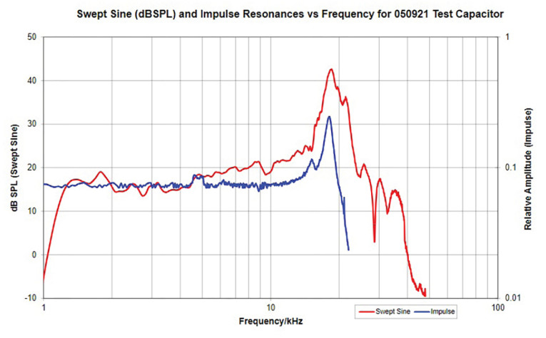
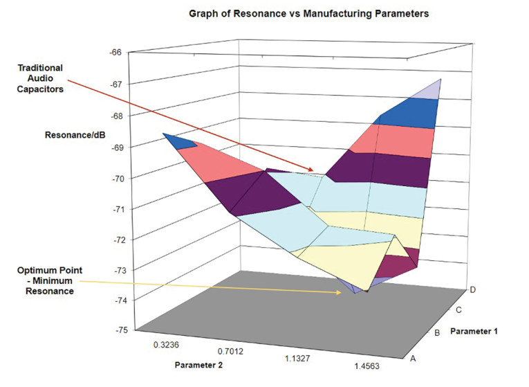
This resonance was measured using a swept sine wave, and impulse excitation, with an instrumentation microphone and was seen in the upper audio frequency band between 10kHz and 30kHz. The resonance by frequency is shown in Figure 1. The mean amplitude varied depending on which capacitor was being tested and, for most capacitors, the emissions were clearly audible.
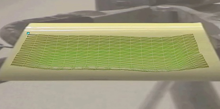
The research team then used a laser scanning vibrometer to scan multiple points over the surface of the capacitor to provide accurate measurement of surface displacement. The three-dimensional graphs that were generated represented the movement of the surface. By overlaying these graphs onto images taken from a video camera, it was possible to identify the parts of the capacitor that were experiencing surface disturbance.
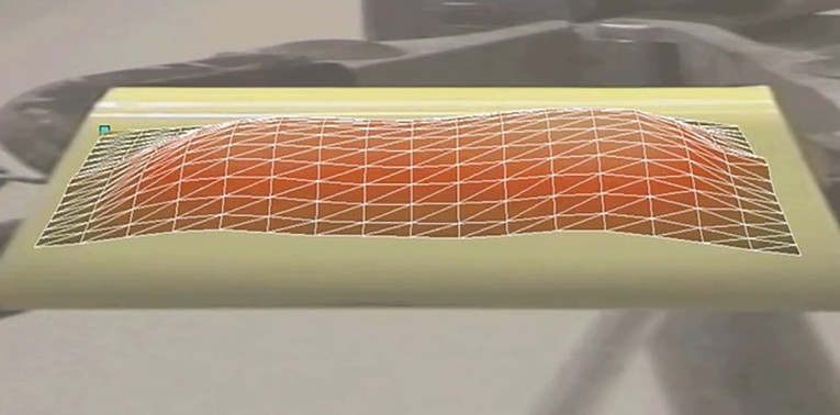
The presence of a resonant mode was shown by the nodal point in the middle of the capacitor body, in Figure 2, and by the areas of the capacitor body that demonstrated maximum surface displacement, shown in Figure 3. While the earlier research demonstrated no difference in electrical or acoustic measurements, scanning with a vibrometer showed that mechanical resonance does vary across individual capacitors.
The resonant signature of each capacitor is determined by the physical dimensions as well as by the properties of the material and the processes used to manufacture the capacitor. The next stage of the research was to assess whether the mechanical resonance delivered a change in the quality of the sound that was reproduced.
The difference in sound produced by two different metallized film capacitors in the high-frequency driver circuit of a first-order crossover is very slight. It is possible that this difference could only be detected by a listener trained to critically evaluate and develop audio systems. Many hours of listening tests were essential to verify the impact of mechanical resonance on the quality of sound reproduction.
For these tests, ClarityCap and the University of Salford Institute of Acoustics completed a total of 33 blind listening tests. The results showed that the capacitors optimized to reduce resonance reproduced sound with greater clarity and spatial information.
Experiments in design, as well as in manufacturing processes, identified two production variables that were differentiators in minimizing capacitor resonance. ClarityCap used the research to develop an optimized series of capacitors, which were designed to reduce resonance. The SA series of capacitors already exhibited low resonance, but this was further optimized to achieve a reduction in resonance of 4.3dB, and the introduction of the Enhanced SA (ESA) series of capacitors.
A standard manufacturing process was followed, with particular focus on the production variables. The pure aluminum metallization was applied to a roll of polypropylene film with a vacuum deposition system, and the roll was slit for winding on a high-speed winder in a 5µm filtered clean room. A metallic contact layer was applied, known as schoopage, before the capacitors were heat-treated to remove areas of stress in the winding and expel any remaining air-pockets, The process also hardened the winding once it has cooled back to room temperature.
Defects in the winding were removed by the clearing process in which high voltage is applied. This cleared areas that had an inherent issue in the film or metallization, or an impurity that had been picked up during the winding or building process. The clearing process was used to effectively vaporize a very small area of the metallization. The next stage was to select a metallization pattern that could minimize resonance.
The pattern of the metallization is typically adjusted for different voltages, current-ratings, or ESR, as well as to increase safety by functioning as a fuse. In a standard winding, one metallized film is wound on top of another to create two parallel conductors with a separate dielectric. However, ClarityCap used a metallization pattern that is widely used in industry, but not for manufacturing audio capacitors. This had the effect of breaking up the active sections of the capacitors into smaller sections, and reducing the overall resonance, as shown in Figure 4.
The metallization pattern was used to produce the Minimum Resonance (MR) series of capacitors and the result was that reduced resonance was delivered, with minimal impact on the ESR value.
The Role of Resin and Copper
While minimizing resonance was the start of transforming the delivery of audio quality, other technologies were added to improve signal propagation in addition to reducing distortion and phase shift.
Hardness testing in an Aeronautical Laboratory showed that a standard polyurethane resin can provide some damping but remains too soft to restrict the displacement in the capacitor. The use of an epoxy resin provided the best results, providing a lower level of damping but enabling the capacitor to increase audio quality by achieving excellent restriction of displacement.
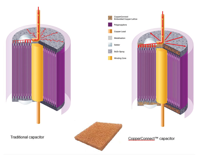
Another new development was the addition of a 1mm copper lattice embedded at both ends of the capacitor. The CopperConnect technology improved the electrical interface between the capacitor lead and the capacitor electrodes, which are Zinc sprayed. This delivered a reduction in the grain boundary crossings at the ends of the capacitor, and the introduction of narrower films delivered lower ESR. Another benefit was that the 1.0mm2 copper leads were oxygen free.
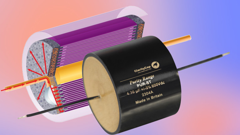
The minimum-resonance metallization pattern and CopperConnect technology were initially combined in the CMR capacitors, and then in the latest Purity capacitors, which added more enhancements, as shown in Figure 5.
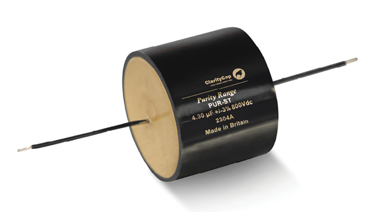
In addition to extending the CopperConnect lattice to a 10mm thickness, the Purity capacitors achieve voltage up to 800V DC and add a silver-coated multi-strand Van den Hul cable, see Figure 6. This cable is already used by many high-end speaker manufacturers and provides an easy path for high frequencies to reach the tweeter to deliver accurate audio reproduction.
The new capacitors are already being used in crossovers by several high-end loudspeaker manufacturers. Development is ongoing, and more innovations will follow to ensure that capacitors continue to play a vital role in delivering the highest achievable levels of audible performance. aX
Resources
“Capacitor Resonance,” Charcroft Electronics, Ltd., www.claritycap.co.uk/research
This article was originally published in audioXpress, January 2024
 About the Author
Roger Tall is a director of ClarityCap and Charcroft Electronics and has had an interest in audio and music from an early age. In the 1980s, he created mix-tapes, followed by sound-engineering live events, and producing optimized, well-mixed, and balanced sound using analogue and digital mixing desks. As well as attending local live-music concerts, Roger admits to having three hi-fi systems at home. The technical support that Roger gives to manufacturers of high-end audio equipment starts with selecting the right capacitor for each application, and adds lateral thinking to follow the development through to the launch and beyond.