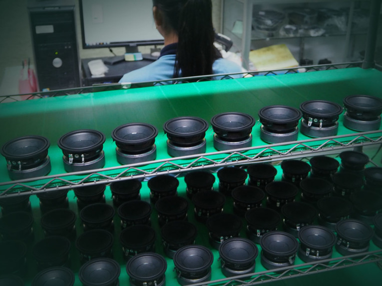
Every production facility has one priority: to build products that meet the specifications with the greatest efficiency and highest yield possible for optimum profitability. Think about what that means for end-of-line tests. Their goal is to have as many units pass as possible. Tests must be fast to avoid slowing down the production line, and the test environment is generally noisy, often with variable temperature and humidity. The quest for high yields and manufacturing efficiency, along with challenging operating conditions and sometimes poor training, can result in unreliable measurements. When this happens, the only loser is you and your brand’s reputation.
I’ll never forget being told about a production line operator who increased pass-rate by opening the test box during measurements so that the factory background noise would mask the high-order harmonics to fool the perceptual Rub & Buzz algorithm. This might improve his yield, but it’s not so good when these products ship to customers! While this is one of the more outrageous violations of end-of-line test protocol, I have also seen many other questionable measurement practices over the years. In this article, I’ll try to de-mystify production tests and look at some simple measures that you can take to ensure a smooth transition.
Production Line Test Considerations
Production line measurements differ considerably from R&D testing. In the design phase, you carefully select transducers and components, engineer signal processing algorithms, measure performance with different materials and components, and measure and re-measure parameters that affect the listener experience such as frequency response, directionality, distortion, and more. These measurements should be calibrated, and are often made in an anechoic chamber or with a test system that replicates anechoic conditions using a simulated free-field technique. The environment is usually fairly quiet, and can be controlled when making measurements (e.g., by turning off noisy air conditioning or refraining from talking). The time taken to make and analyze measurements is usually not critical, and you can use time-consuming workarounds, such as exporting data for additional analysis to extend the capabilities of your test system.
There are several major changes when you move into production. Speed is critically important, whether your measurements are in-line on the conveyor belt, or offline in a test box. Factories are inherently noisy and both the physical setup and test system need to minimize the effect of background noise. Any product is likely to measure differently under production line conditions compared to the laboratory. For this reason, end-of-line measurements are generally relative to either a golden unit or statistical average rather than absolute measurements that can be reproduced in any test lab. Limit setting is tricky and needs to be approached carefully, taking into account a variety of factors. Finally, different parameters such as Rub & Buzz and loose particles are measured to account for manufacturing-induced defects.
Speed vs. Accuracy
Most transducer production line tests are completed in a second or two. While there are ways to optimize tests for speed, the biggest factor is probably the test system. Speed is one of the main differentiating factors between lower cost “hobbyist” test systems and a true professional-grade product. While most manufacturers claim “fast testing,” it’s important to ascertain how long it will take to make the specific measurements required. For example, can the system make both perceptual and traditional measurements simultaneously with just one sweep of the stimulus, or are two test sweeps needed, doubling the test time? Can electrical measurements such as impedance be measured at the same time as acoustic properties? Are the algorithms optimized for fast measurements? Will the results be accurate and repeatable with fast sine sweeps, or is it necessary to sweep the signal slower to get consistent results? You can create a test signal as short and fast as you like, but if the test system cannot return repeatable results at that speed, it’s pointless!
Aside from the test system, there are other techniques you can use to minimize test time. These include sweeping from high to low frequencies to minimize transducer settling time, sweeping only over the frequency range of interest, and using the lowest resolution necessary to obtain repeatable and reliable results, which may vary across different parts of the frequency range.
Noise Immunity
Noise is rarely a problem in a laboratory setting. Measurements are often made in an anechoic chamber or a test box, and even in an untreated room, the environment can be controlled. This is not the case for production lines. Background noise in the region of 80dBSPL to 100dBSPL is common, especially at low frequencies and there is usually a mixture of continuous noise (e.g., machinery hum or air conditioning) and transient noise (e.g., air compressors, intermittent machinery noise, etc.). These background noises can mask production line defects—as my manufacturing friend once demonstrated, it’s easy to get a speaker with bad Rub & Buzz to pass if you open the test box and add a little background noise to mask the high-order distortion harmonics.
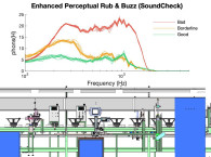
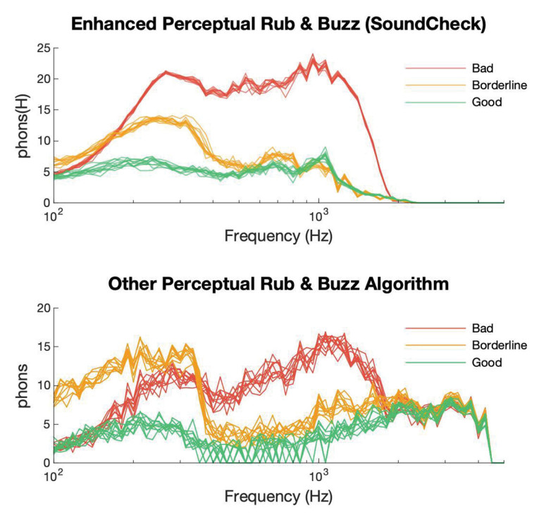
A significant factor in mitigating background noise is the test system itself. Good production line test systems feature filtering algorithms designed for noise immunity as well as speed. This has always been a focus at Listen, with the introduction of many unique algorithms to minimize the effects of background noise throughout our entire 27 year history. This is illustrated in Figure 1, which shows the repeatability of SoundCheck’s enhanced Perceptual Rub & Buzz (ePRB) algorithm, specifically designed for production line tests, vs. a perceptual Rub & Buzz algorithm from a different manufacturer. Interestingly, this is where I often see manufacturers who have designed their own test systems stumble—it’s much easier to write a Matlab or Python algorithm that measures correctly in a quiet environment than it is to write one that will measure it accurately in a noisy factory.
Acoustic isolation is also significant in minimizing background noise. Simple products such as transducers are usually tested in-line, with acoustic panels around the test station. Products that require more complex fixturing, such as VR headsets, headphones, and so on are usually measured offline in an acoustic test box. These test stations generally offer better acoustic isolation, but correctly designing a test box is no easy task. It is important to minimize reflections, from both the test box and the fixture, particularly those that cause sharp reflections or dips, as these affect measurements the most. This can be particularly challenging when there are metal test fixtures inside the chamber. Higher frequencies also pose reflection challenges; since the wavelengths are small, minor differences in microphone positioning change the frequency of the reflection, making it hard to create limits.
There are many systems integrators specializing in test boxes and in-line test equipment that can usually combine your test system of choice with their hardware. Photo 1 shows the AB41 end-of-line test chamber from Bojay, a China-headquartered systems integrator that works with many manufacturing facilities worldwide. This particular chamber has internal dimensions of approximately 0.5m × 0.5m × 0.75m, and is designed for testing small products such as drivers, smart devices, cellphones, VR headsets, and so forth. It can attenuate external background noise by up to 40dB inside the chamber, reducing factory noise levels sufficiently to provide accurate results. The internal mounting fixture can be customized depending on the product.

Limits
As I mentioned earlier, production line measurements tend to be relative rather than absolute, as differences in test fixtures, background noise and measurement type make it virtually impossible to correlate production results with R&D measurements. Typically, production measurements are made relative to a golden unit or a statistical average, with floating limits. The golden unit may need to be frequently re-measured, and limits re-calculated if environmental conditions such as temperature and humidity vary significantly over time.
Limits may need to float in both level and frequency to overcome reflections from fixturing and from the test box itself. When configuring limits, devices need to be measured multiple times for Gage R&R to understand any variation in the product measurement positioning and to ensure measurement repeatability. There is often a certain amount of trial and error involved in setting limits, tweaking them until there is acceptable yield and good correlation with human listeners. Correctly setting limits is an extremely complex process and to cover it thoroughly would be a whole article in itself. When beginning production of your device, it’s well worth being on-site to assist with limit-setting, so that you can truly see and hear what is going on.
There is some hope that limit setting will become simpler in the future with the trend toward artificial intelligence and perceptual models for characteristics such as Rub & Buzz and loose particles. These measurements have simple level limits that usually remain constant across the frequency range, making them extremely fast and simple to configure.
What to Measure
Most laboratory measurements are not relevant on the production line. Conversely, there are measurements for manufacturing-introduced defects that have probably not been measured during product development.
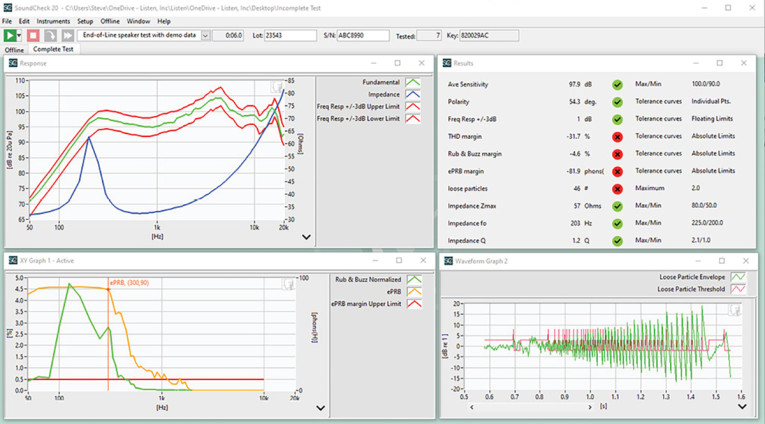
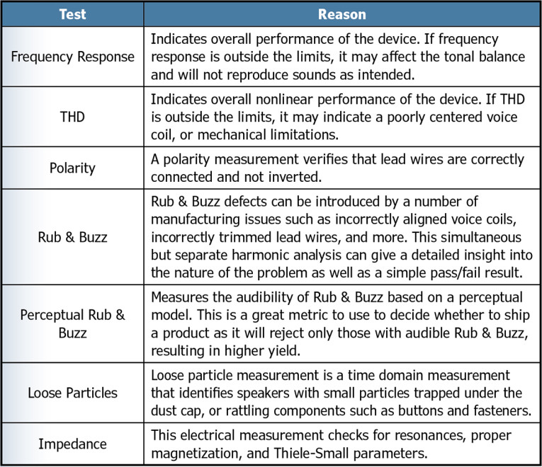
Production line tests, as shown in Figure 2, measure overall performance parameters such as frequency response and THD to ensure that it is within specification, and also make measurements to identify manufacturing errors, such as reversed polarity, Rub & Buzz and loose particles. Table 1 shows typical manufacturing transducer tests, along with the rationale behind measuring these parameters. This will vary depending on your specific product, but a list of specific measurements is a good starting point as you start to develop your production tests.
While the majority of test methods have remained similar since their introduction in the late 1990s and early 2000s, the industry is shifting toward perceptual measurements for identification of manufacturing defects. Perceptual measurements use a model based on the human ear to identify only those faults, which are audible rather than harmonic or time-based analysis to identify all defects, audible or not.
These methods offer two significant advantages over traditional methods. Most significantly, they result in higher yield with no perceived quality degradation, as products with inaudible defects are not rejected. Perceptual methods are also very simple to configure and set limits. The limit is typically a flat line across the frequency spectrum based on a known level of audibility which often will remain constant across multiple products. That said, there is valuable additional information about your production line to be gleaned from also making conventional distortion measurements. Some test systems can do both simultaneously with no increase in test time, giving you the best of both worlds.
Test Equipment
We have already discussed how production line test equipment needs to be fast, noise-immune, and flexible to offer the range of tests that you need now and in the future as technology evolves. But what are the other distinctions between a production test system and the configuration you might be used to in the laboratory? Generally speaking, production applications require a much-reduced feature set, as flexibility for a wide range of highly customized laboratory tests is not needed. Because of this, the price-point is lower.
While some manufacturers promote a separate low-cost system for end-of-line tests, at Listen we have taken a modular approach to both software and hardware, with a production system coming in at approximately 50% the cost of a laboratory-grade system. This approach maintains seamless compatibility between manufacturing and development, so tests can be created and modified using an R&D system and sent to production for implementation. Conversely, production line results can be emailed back to the R&D lab for more detailed analysis to aid with any troubleshooting. This modular approach also ensures future compatibility. Technology is evolving at a rapid pace, and the ability to adapt to new digital interfaces such as A2B, or increase the channel count of your test software to measure microphone arrays that might be required for a new product, offers peace of mind.
Production lines also have different hardware requirements. In the laboratory, flexibility is key, and engineers are generally fairly comfortable with changing the setup as needed. Once you get into production, ease of use and error-proofing become the driving factors as the test operator likely has minimal acoustic knowledge. Incorrect setup or accidental configuration changes might not even be noticed unless units start failing.
We’ve promoted software and sound-card-based systems for more than 25 years now, and although the third-party audio interfaces we recommend, such as RME and Lynx, offer excellent performance, they have their disadvantages when used in a production setting. Between the computer, sound card and the ancillary components such as amplifiers, microphones and microphone power supplies, there are many cables that need to be connected correctly. These professional sound cards also have many front panel controls, including gain adjustment. You can probably imagine what happens if a gain knob is accidentally knocked mid-way through a production run. These potential pitfalls inspired us to develop our own range of audio interfaces which include all the equipment needed for basic audio tests in one chassis with just a single USB connection to the computer.
Products in the AmpConnect family include audio inputs and outputs, microphone power supply, amplifier, impedance measurement, and digital I/O and an amplifier. The smaller, low-cost AudioConnect range offers just the audio interface plus microphone power and a headphone amplifier. All cabling and switching is internal to these devices, preventing cabling errors. Our newer interfaces are also completely free from knobs on the front panel, eliminating any accidental configuration changes; all control is via the test sequence or computer. Naturally, space and cost savings are also achieved by using a single hardware unit rather than separate components.
No matter what combination of hardware and software you choose for your audio test, it is important to ensure that they work well together and that you can calibrate the entire test system as a whole.
Test System Integrity & Specification
The more tightly you specify your tests, the more consistent your end product will be. As I mentioned in the introduction, your production facility aims to produce products that meet your specifications with the highest possible yield and therefore profitability. This means there is little to be gained by testing more thoroughly than dictated by the terms of your contract, and this places the burden on you to be specific. There is a big difference between specifying “frequency response within 3dB of golden unit” and specifying “frequency response within 3dB of golden unit measured with SoundCheck Version 20 and AmpConnect 621 with the provided test sequence in a well controlled test environment.”
Without the additional detail in the second option, your manufacturer could be using any test system, which may not measure as accurately as you expect. They may be pairing a software-based system with an inadequate audio interface, for example one that is too noisy or has phase issues that lead to incorrect measurements. Even worse, they might be using a pirated version of a reputable software system! These have a whole host of problems including security issues, older versions of the software without the latest algorithms, look-alike or imitation products that simply do not measure correctly, and of course lack of manufacturer support and upgrades.
At the very least, it is advisable to fully specify the software, down to the current version number, the specific software configuration that is required to run all your tests, and the official authorized vendor from which they must purchase it. Many large OEMs go one step further, purchasing it themselves for their contract manufacturer to guarantee system integrity. If you are relying on your contract manufacturer to purchase the software, it is advisable to ascertain the serial numbers of the systems they plan to use on your lines, and verify their authenticity with the manufacturer.
Hardware is also important. It is critical to use an audio interface with sufficient dynamic and frequency range, and it is also important that it can be fully calibrated with the software. Many times I have witnessed a manufacturer spend good money on a professional audio measurement system, only to attempt to save money by pairing it with a low-cost sound card that is not good enough to get consistent results. It does not need to be the same interface that you use in the lab, as there is often a cheaper alternative that will be adequate for production testing, but do take the advice of your system provider, and ensure that the hardware is also clearly specified in your test plan.
These days, most quality-driven OEMs provide their manufacturer with the specific tests that need to be implemented. With software-based systems, test sequences are easily shared via email, network or USB drive. Mindful of the concerns that some OEMs have when sharing their test sequences outside of their direct organizations, SoundCheck now includes additional security features to maintain security and control of the entire test procedure. Measurement sequences can now be locked and protected, preventing operator modification and also ensuring that the sequence cannot even be viewed or opened without a password. This offers complete test confidentiality and security, preventing the test from being modified, copied, or re-created for use with other products. Test sequences can also be locked to specific SoundCheck serial numbers, to ensure that all measurements are being made on legitimate SoundCheck systems.
Factory Integration
Manufacturing environments often require the test system to be integrated with databases and larger factory automation systems. When specifying a test system, consider what data you need to collect and maintain, both now and in the future. Some companies rely entirely on only a pass/fail result, whereas others save all test data to a database or data management system. Many contract manufacturers are now required to save data to the OEMs own database for full traceability. Whatever you need to do, check that your test system offers suitable capabilities and specify how this should be configured.
While production line tests for simple products such as drivers, microspeakers, and earphones tend to be fairly stand-alone, audio tests are often one small part of the overall test plan for more complex devices. In these cases, screen tests, connectivity checks, and other inspections may also take place alongside the audio measurements, and the audio tests must be controlled by a larger test automation system. Every manufacturer implements this differently. SoundCheck uses TCP/IP control, which offers control in any programming language that can provide TCP/IP commands. These commands can not only start and stop tests, but also import and use data stored outside of SoundCheck such as limit curves, start and stop frequencies, and more. While such advanced functionality requires considerable expertise to implement, it does allow professional audio testing with all its advanced techniques and algorithms to be fully integrated into a highly customized test environment.
Operator Instructions & Ease of Use
Document everything! This may seem like common sense, but specific, clearly documented operating instructions, covering everything from initial system configuration, wiring diagrams, and daily system test and calibration directions, to precise instructions about positioning and fixturing, and procedures for a failing test (reject or re-test) will improve your test integrity. If you are providing test sequences to your manufacturers, it’s easy to include instructions, either verbal, pictorial, or even video within the test sequence to ensure accurate positioning and other operator interaction during the test, in addition to the stand-alone documentation. Knowledge transfer has been extremely challenging over the last couple of years due to travel restrictions, so it is more important than ever to ensure that all production test operators are adequately trained.
Conclusions
In summary, production testing is complex, and your product quality is only as good as your test system and your system tests. That said, there are several things you can do to ensure a smooth transition:
- Take the time to understand the differences between laboratory and production tests, and what you need to measure.
- Thoroughly evaluate and completely specify the test system for current and potential future needs.
- Set realistic and appropriate production test limits. Know the practical limitations of your test environment (e.g. fixturing and test box), your test system, your manufacturing and product tolerances, and adjust your limits appropriately.
- Clearly document and communicate all test requirements including equipment, tests, environment, and operating instructions.
This article was originally published in audioXpress, March 2023


