Holoplot is a Berlin, Germany-based pro audio company and manufacturer of innovative 3D professional audio technology, the X1 Matrix Array. X1 is made up of two audio modules — Modul 96 (MD96), a two-way module integrating 96 drivers in a two-layered matrix design, and Modul 80-S (MD80-S), a three-way module with 80 drivers in its first two matrix layers and a sensor-controlled subwoofer driver in its third layer. This matrix arrangement of loudspeaker drivers of different sizes — in a unique multi-layered configuration — enables control over sound propagation across a large frequency range, while providing the SPL and quality desired for high-performance sound reproduction.
Opposed to conventional loudspeakers relying mostly on hardware design, X1 is software-driven, combining Wave Field Synthesis and 3D Audio-Beamforming to achieve authentic sound localization and complete control over the beam shape. It’s the first sound system to decouple sound from its source, enabling the positioning of virtual loudspeakers within a space, creating sonic freedom for the user and exceptional experiences for the audience. X1 is able to generate multiple simultaneously running sound fields, each with its own content, level, shape, and position — all generated from as little as one module.
To develop such complex solutions, a balance between simulation and measurement during the development process is key to ensure continuous verification and improvement of the models and algorithms as well as the enhancement of sound quality. This process requires an extremely advanced measurement solution, which is why Holoplot turned to Klippel for its expertise.
With the Near Field Scanner (NFS) System, Klippel — an innovative leader in providing unique test equipment for electro-acoustic transducers and audio systems — has created a new approach for directivity testing in loudspeakers. This measurement system has been instrumental in the ongoing development of Holoplot’s X1 Matrix Array.
The NFS System is considered a state-of-the-art technology to capture the full acoustic characteristics of transducers used in every loudspeaker design.
From early on, the development of X1 and the underlying Holoplot technology has been served by the data acquired using Klippel’s NFS Carousel. On the design side of the Matrix Array, the electroacoustic design, modeling, and validation were a complex procedure due to the multi-layered design of the array, especially the MD80-S one with the subwoofer driver.
Acoustically speaking, the integration and interference between each speaker layer in the Matrix Array are extremely important to capture in order to achieve the best simulations and performance of the driving algorithms. The underlying optimization algorithms built into the Holoplot technology require the highest precision, three-dimensional information from each transducer-type built into each of the X1 modules.
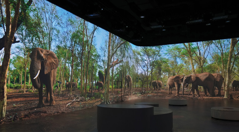
The benefits that Klippel and the NFS offered Holoplot are best explained by the collaboration and testing around the Illuminarium Atlanta deployment (Figure 1). Illuminarium is at the forefront of fully immersive experiences, placing audiences “inside” the narrative with techniques used in traditional motion picture production and virtual reality that facilitate the experience of real-world, filmed content (e.g., a safari) and authentic, re-created worlds in an immersive environment.
The Challenge
X1 contributes to this experience by delivering unprecedented authenticity of sound reproduction, perfectly matched with the video projection. While Holoplot’s Wave Field Synthesis and 3D Audio-Beamforming technology enables the creation of authentic audio objects, the immersive nature of Illuminarium Atlanta’s Wild: A Safari Experience presented an additional challenge to solve — finding a way to completely hide the X1 modules installed throughout the venue behind a seamless projection surface, without compromising on the system’s peerless sound quality and control.
Concealing any sound system behind an acoustically semi-transparent panel leads to absorbed or reflected acoustic energy, resulting in gain changes in the audio spectrum. The Transmission Function (TF) is the frequency-dependent reduction or amplification in the sound level of a sound source as it passes through the panel used to conceal the sound system.
Traditionally, the compensation of the concealed speaker’s TF is achieved by equalizing the average TF across multiple angles or simply taking the TF on-axis and applying the inverse curve as the profile of an equalization stage. A preliminary assessment of the TF in the anechoic chamber led to the conclusion that the evaluated panel introduced very different gain variations to varying angles for the same frequency.
As a result, the spectral balance across the audience area would be considerably different at different angles and distances to the concealed audio module, reducing spectral homogeneity. A TF compensation as described would not be sufficient, but rather an angle-dependent, Spatial Transmission Function compensation would be required.
The Solution
Holoplot Wave Field Synthesis and 3D Audio-Beamforming technology rely on high-resolution sensitivity and 3D directivity balloons from the transducers built into the audio module. Holoplot obtained the necessary data from Klippel’s NFS service during the design and development stage of X1. Using 3D Audio-Beamforming algorithms, Holoplot can define custom-shaped wavefronts using level and phase manipulation that fully adapt to the audience area. Furthermore, the resulting wavefronts are optimized for spatial and spectral homogeneity by taking a reference target curve.
Once the Spatial Transmission Function compensation became a challenge to solve, an opportunity arose; a solution to improve the spectral balance in 3D space of concealed audio modules already seemed to be part of Holoplot’s core technology capabilities.
If Holoplot’s algorithms were aware of the Spatial Transmission Function introduced by the acoustic panel in front, the optimization and equalization engine would compensate for the effect of the panel in any direction, and not only on-axis, performing similarly as if the panel would not be present. Changes in the transducer’s radiation balloon caused by panel resonances, reflections, or acoustic absorption at specific angles would be known in advance and partially counteracted to achieve the desired spectral profile across the audience area.
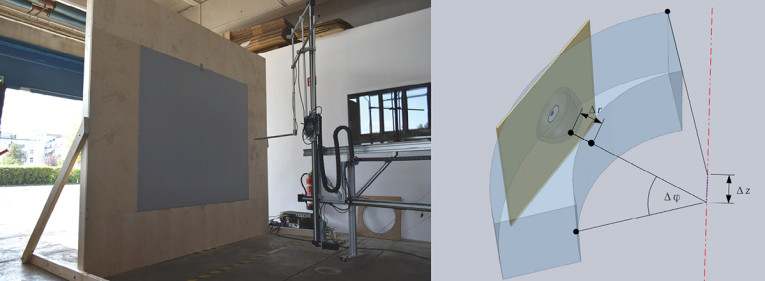
This approach presented a requirement to be solved by Klippel — capturing the transducer’s directivity balloon when deployed behind the carbon fiber panel as used in the actual application at Illuminiarum (Figure 2).

The Near Field Scanner
Klippel’s NFS Carousel uses a holographic measurement approach to determine the directivity of a loudspeaker. This method uses special solutions of the wave equation (spherical harmonics, Hankel function) to determine the 3D sound pressure output of the audio device. Compared to traditional measurement techniques this provides more comprehensive and accurate measurement data while minimizing costs (e.g., for an expensive measurement room) and measurement time.
The device under test (DUT) remains at a fixed position in the center of the scanner. This simplifies the handling of heavy devices and ensures constant room excitation and therefore constant room reflections during the scanning process. The robot arm moves a microphone around the device under test and captures the sound pressure in the near field.
Due to the scanning along a double layer, the Direct Sound Separation (Klippel’s patented technology) uses the additional phase information to detect the direction of the sound wave and can remove all room reflections from the direct sound of the loudspeaker. Thus, the measurement system provides accurate free field data in any environment (e.g., a workshop or office).
The Measurements
To answer the question of the interaction and influence of an acoustically semi-transparent panel on the audio quality of X1 a few different testing scenarios were run.
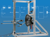
At first, a standard full-space 4π measurement was performed with the DUT placed in the center of the NFS Carousel. Figure 3 shows the X1 Modul 80-S mounted on the scanner.

Second, the X1 audio module was placed behind the semi-transparent panel, mounted in a baffle. Usually, half-space scans in 2π are performed in a similar setup with a baffle mounted in the center of the NFS Carousel. However, the overall size and weight of the construction and the special positioning conditions of the X1 audio module made this setup difficult. For this reason, the baffle construction was built up next to hardware on the floor of the workshop and the microphone arm of the scanner was turned to the outside by additional poles to put the microphone into position (Figure 4a). Figure 4b visualizes the movement range of the microphone in this setup (the blue surface).
The sound field is scanned on a hemisphere in front of the baffle. By using symmetry conditions of the basic functions, the same spherical wave expansion can be adapted to such a half space measurement in 2π.
To achieve perfect half space conditions, the NFS measurement principle only requires a baffle that is slightly larger than the measurement surface, because effects of the baffle (e.g., diffraction) can be removed by Klippel’s Direct Sound Separation technology.
For the measurement, the Klippel Analyzer (KA3) was directly connected to the speaker terminals of the individual transducers. Such a setup is useful to get a clean set of acoustic transfer functions without any influence of a DSP or smart amplifier. In total, multiple transducers were scanned as well as tweeters and woofers, which can be comfortably done using the Klippel Multiplexer hardware to switch between the drivers and shortcut inactive channels automatically.
The Results
An exemplary pair of woofer and tweeter was used to evaluate the effect of the acoustic panel used to conceal the audio module. It’s important to note that, as the nearfield measurements do not include any signal processing, the spectral performance out of the transducer’s working range is shown as well. The frequency responses of each transducer with and without the acoustic panel are shown in Figure 5.
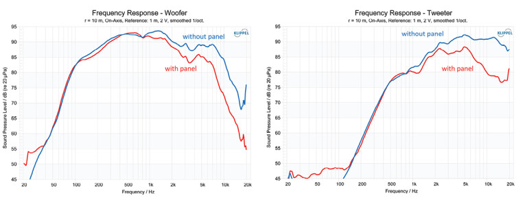
Comparing the acoustical output of both measurements shows a transmission loss in the on-axis frequency response. Using a traditional approach, these frequency responses would be a base to calculate the transmission gain and compensate for this loss of energy with a DSP. However, considering also the off-axis responses, the acoustic semi-transparent panel causes other disturbances. There are additional resonances that affect the radiation pattern at certain frequencies, especially in the range between 2kHz and 5kHz. Above 7kHz the measurements show higher transmission losses on-axis than off-axis, resulting in a lower directivity index and a slightly wider coverage angle when the panel is attached.
The Spatial Transmission Function of the acoustic panel shown in Figure 6 pictures the angle dependency of gain changes across the spectrum. The Spatial Transmission Function is the absolute spectral gain difference between the bare transducer and the same transducer behind the acoustic panel after applying frequency smoothing of 1 octave and spatial smoothing of 15°. The spatial smoothing was applied so that isolated artifacts introduced by the panel used for measurements would not be introduced in the generic compensation to other panels with different properties: bracing differences, panel stiffness, and manufacturing variations or slight panel positioning differences.

To illustrate the benefit of the Holoplot 3D Audio-Beamforming approach compared to conventional audio solutions, the 3kHz frequency has been used as an example in Figure 6. The level difference between the 0º (on-axis) and 45º is approximately 2dB; hence, any global spectral correction at 2kHz would work effectively for one angle but over, or under-compensating at other angles.
Spatial Transmission Function differences are challenging to solve with a single, global equalizer. On the other hand, using Holoplot’s 3D spectral compensation as part of the optimization engine, the transducers used to render the beam, can be individually spatially equalized, resulting in optimal spectral balance as the listener moves across the audience area.
Once the X1 transducer balloon data is corrected using the Spatial Transmission Function of the panel and included in Holoplot’s algorithms as an audio module variant, concealed X1 audio modules can be optimized, simulated, and benchmarked.
Figure 7 shows exemplary transfer functions of an optimized beam with a 120º opening angle under different scenarios for different angles (0º, 30º, and 60º) at 1/3 octave resolution: a plain Holoplot MD96 audio module (black), the same module and beam configuration concealed with the MDI panel in front (red), and finally the Holoplot MD96 audio module concealed with the MDI panel and spatially compensated using Holoplot algorithms.
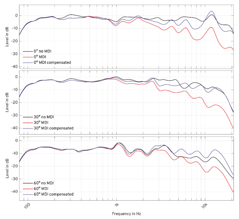
Figure 7 clearly illustrates the different spectral variations at different angles, which can only be solved with individual equalization. Holoplot’s spatial compensation for the acoustic panel was implemented to restore overall spectral balance to the desired frequency response. Isolated local artifacts or spectral coloration resulting from panel resonances or reflections were not part of the correction, as compensating for these has proven ineffective.
Conclusion
Audio systems can be concealed in a variety of ways. Materials, such as cloth or perforated screens that are acoustically transparent, let sound pass through with minimal acoustic performance loss and can be effective in specific settings.
None of these solutions were feasible for the Illuminarium project as they cause visible distortions in the projection mapping of video content. To overcome this, Holoplot partnered with Canadian company MDI Strong, which developed a high-resolution video projection solution using a micro-perforated carbon fiber panel. This proved highly effective in providing a seamless projection surface, but introduced some disadvantages for the sound system concealed behind it, namely angle-dependent transfer function variations.
Klippel’s NFS System has proven an effective and robust way to capture any loudspeaker’s directivity balloon, including those concealed behind a panel. Capturing the three-dimensional behavior of the drivers mounted in the X1 audio modules and when deployed behind the MDI panel gave Holoplot the data required to implement the spatial spectral balance correction.
The spectral balance correction counteracts the level differences between different angles in 3D space for the same frequency across the audio spectrum. This newly developed feature for the Illuminarium project increased the spectral homogeneity of the deployed audio beams considerably and presents a clear advantage over traditional compensation methods used otherwise.
The result of this study is a concealing method for Holoplot X1 Matrix Arrays that delivers a clear, full-range sound with improved spectral homogeneity and a completely unobstructed visual projection surface. aX
 About the Authors
Adrián Lara Moreno is head of Research at Holoplot. Adrián joined the company in 2011 as a DSP Engineer, researching Matrix Array concepts together with Helmut Oellers, the founding father of Holoplot technology. Adrián played a pivotal role in creating Orion, Holoplot’s first loudspeaker and proof-of-concept product. Adrián’s progression to Head of Research has been instrumental in delivering X1 as well as driving Holoplot’s further product development.
 Christian Bellmann studied mechatronics at Dresden University of Technology with a focus on control engineering, power electronics, and electrical drives. In 2013 he received a Diploma degree for his thesis “Separation of direct sound and room reflections using holographic methods,” which was supervised by Dresden Technical University and Klippel GmbH in Dresden. After graduation, he joined Klippel, where he is currently engaged in the research and development of loudspeaker measurement systems with a focus on acoustical holography.
This article was originally published in audioXpress, December 2022