The use of headsets in communication is increasing, and the demand for improving voice quality in all remote communication continues unabated. While in the past, mostly packaged and corded headsets were used with mobile phones, today’s trend is toward advanced wireless Bluetooth headsets in a completely different price and quality range.
Nevertheless, a huge problem is still using such headsets in noisy situations while simultaneously moving the headset microphones farther away from the talker’s mouth. This comfort for the user results in a substantial decrease in signal-to-noise ratio (SNR) for the talker’s voice signal captured at the headset microphone. The latest technology helping to improve this situation is bone conduction sensors, especially in combination with in-ear headsets. However, testing and optimizing such devices is difficult since no appropriate test equipment is commercially available.
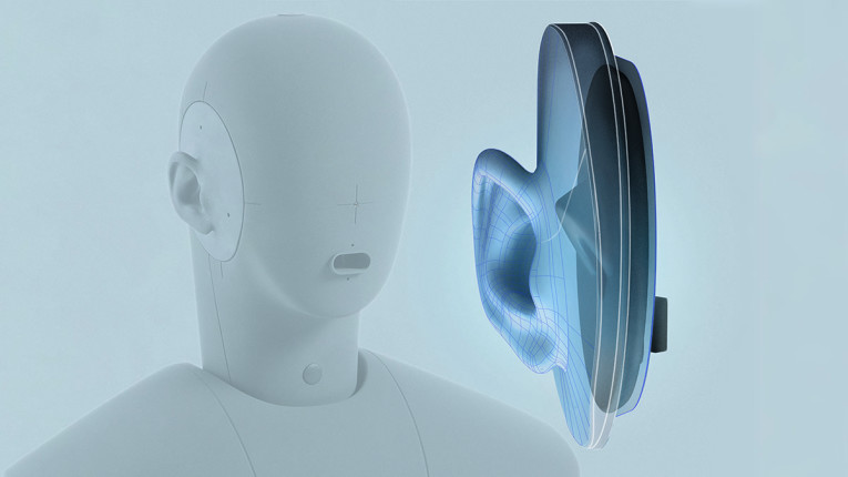
To improve the situation, we complement the HEAD acoustics Head-and-Torso Simulator (HATS) HMS II.3 LN-HEC (with type 4.4 artificial ear according to ITU-T P.57 [1]) with an actuator capable of generating structure-borne sound in the artificial ear. This way, a realistic simulation of the human structure-borne voice signal for in-ear headsets is possible.
This article provides background on human structure-borne sound measurement and simulation; on potential benefits of using structure-borne sound as an additional input signal for headset signal processing; and testing strategies and test results.
Human Structure-Borne Sound — Measurement and Simulation
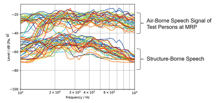
The first step in headset testing with structure-borne sound is understanding the human structure-borne sound transmission of the user’s own voice to the user’s ear, where the bone conduction sensors of headsets are most likely placed. For this purpose, we implemented a structure-borne sensor in an in-ear headset mockup and performed measurements on a variety of human individuals. The goal is to measure the individual spectra of the air-borne and structure-borne sound. These measurements provide an overview of the spread of individual differences and are the basis for deriving average transfer functions.
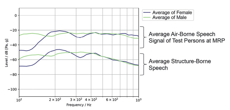
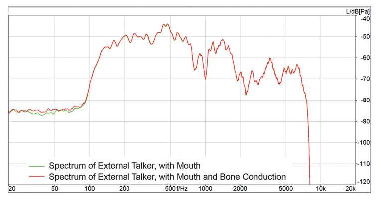
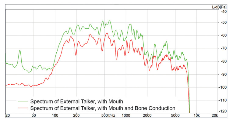
Furthermore, we received information on whether there might be significant differences between males and females. As part of the testing, we conducted measurements with 11 female and 24 male subjects. Figure 1 shows the individual structure-borne signal compared to the air-borne signal at the mouth reference point (MRP). Figure 2 shows the average of these signals for female and male talkers. The difference shows mainly in the frequency range below 300Hz, where female voices generally do not provide any signal energy due to their higher fundamental frequency. Consequently, we chose the average male spectrum as a target spectrum for structure-borne sound simulation.
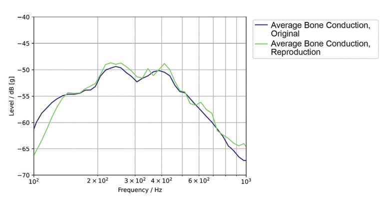
The next step is simulating human structure-borne sound. We extended the artificial head HMS II.3 LN-HEC with an actuator, reproducing the average human structure-borne sound in the artificial ear precisely at the location where we conducted the human measurements. Figure 3 shows the spectrum of the simulated structure-borne sound of the new LN-HEC ear compared to the average human structure-borne sound. Please note that, due to the insufficient SNR of the sensors available today, structure-borne sound simulation currently can only be measured reliably up to 3kHz. As seen in Figure 3, the simulation is correct within a tolerance of ±3dB.
Headset Signal Processing and Potential Improvements with Structure-Borne Sound
The primary purpose of using structure-borne sound in headset signal processing is the improved separation between a near-end talker and near-end background noise, a near-end talker and a near-end impairing talker, and a near-end talker and a far-end talker (double talk detection).
A second benefit of using structure-borne sound could be transmitting the structure-borne signal instead of the near-end microphone signal, at least in the low-frequency domain. The structure-borne signal is almost free of background noise and, therefore, ideally “noise-canceled.”
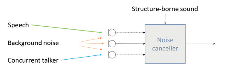
Figure 4 illustrates the signals received at a noise canceller. The separation of near-end speech and impairing signals can significantly improve with a structure-borne signal. What can be expected in terms of enhanced signal processing? The noise canceller is an adaptive filter that estimates the background noise and tries various strategies to reduce background noise by assessing its signal power and trying to minimize the noise level. The better the noise estimation, the better cancellation works.
Separating noise and speech, however, is complex. The noise canceller may diverge, and the speech signal may get degraded. When able to distinguish better between speech and noise based on structure-borne sound, the adaptation control can be much improved. Adaptation can be frozen or adaptation speed reduced, and the noise canceller’s divergence may be avoided.
Consequently, a higher-quality speech signal can be provided in conjunction with low background noise. Similar behavior can be expected with concurrent talkers. Assuming only the voice of the talker wearing the headsets should be transmitted, the concurrent talker can be treated as background noise.
Measurement Results of Actual In-Ear Headsets
We performed measurements of various headsets based on this fundamental research. The test setup is a typical laboratory-based setup using a realistic sound field simulation with eight loudspeakers and pre-recorded background noises, as described in ETSI TS 103 224 [2]. The HATS is placed in the test room, and the headsets are carefully fitted to the HATS. The speech signals used in all experiments are based on Recommendation ITU-T.P501 [3]. Since measurements in steady-state conditions likely won’t show any differences, we created specific test sequences targeting performance differences with bone conduction simulation.
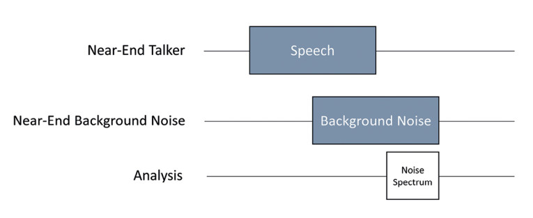
Test sequence A, shown in Figure 5, focuses on the potential divergence of the noise canceller, which may happen if suddenly a background noise situation occurs. In this situation, speech and noise may not be separatable anymore, and speech might get degraded while the noise is not sufficiently canceled.
Measuring the remaining background noise directly after the speech signal has stopped provides a good idea of the noise cancellation performance. The amount of noise reduction indicates the noise canceller’s efficiency in converging reliably even while speech is present. Two example results are given in Figure 6 and Figure 7.
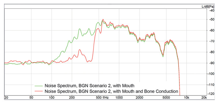
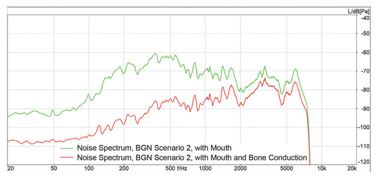
The differences in the remaining noise spectra with and without structure-borne sound are apparent, as well as the difference between the headset performances. While Device 1 provides an improvement of up to 30dB just in the frequency domain up to 500Hz, Device 2 reduces the background noise by up to 30dB over the complete speech spectrum transmitted.
Experiment B
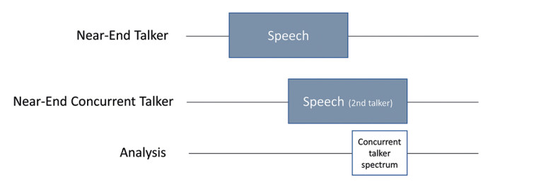
A similar test sequence can be used to evaluate the performance with a concurrent talker present. For this test, no background noise is used. Instead, a second HMS simulates the concurrent talker. The test sequence for this experiment is shown in Figure 8.
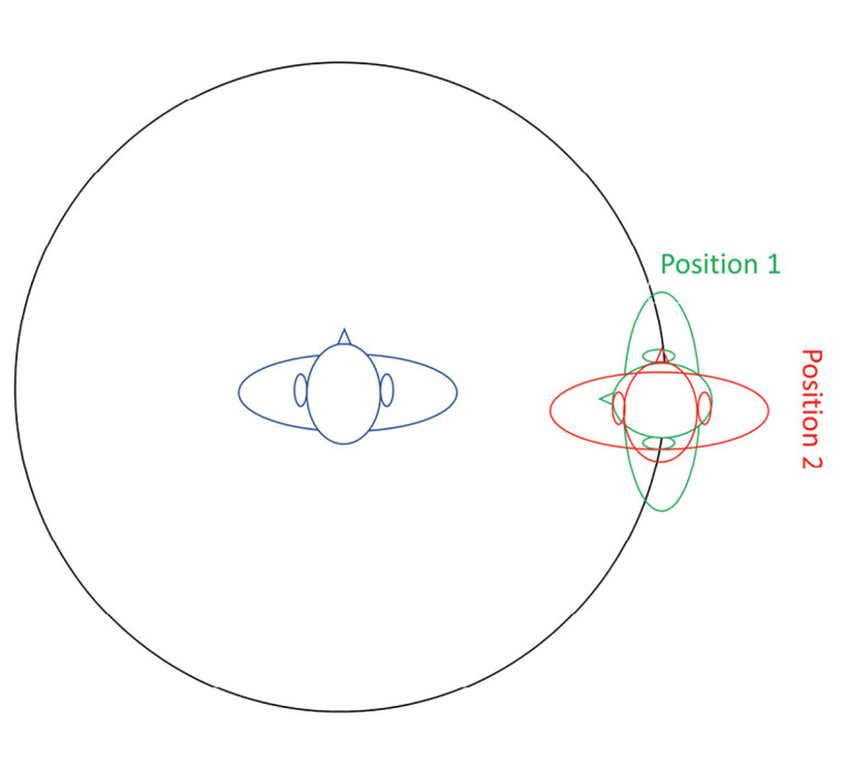
You can use various talker positions in this experiment. In this article, we discuss one specifically interesting combination. Figure 9 shows two concurrent talker positions. In Position 1, the artificial head faces the talker wearing the headsets directly. In Position 2, the concurrent talker is talking in the same direction.
The test results for these two conditions are pretty interesting. While for Device 1, neither a difference between the two positions of the concurrent talker nor a difference between bone conduction simulation nor the lack thereof could be observed (Figure 10).
The result for Device 2 is entirely different. Talkers, facing the wearer of the headset and talking in their direction, are transmitted without any attenuation. When turning 90 degrees, Device 2 differentiates that the second talker may not be talking to the headset wearer anymore and seems to be treated like background noise if bone conduction is present (Figure 11). The attenuation is about 10dB.
Experiment C
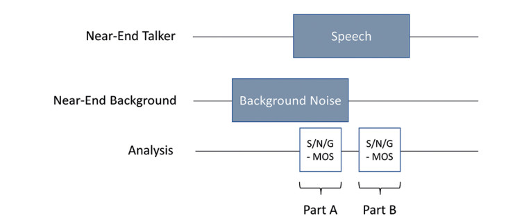
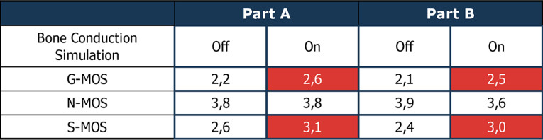
A third test used the following test sequence shown in Figure 12. This test focuses on the noise canceller’s potential divergence if speech is presented after background noise. Here we focus on the speech signal (S-MOS) deterioration and a change in noise reduction performance. A perceptually motivated procedure for such evaluations is 3QUEST [5], as per ETSI TS 103 281 [6], which allows for measuring these differences.
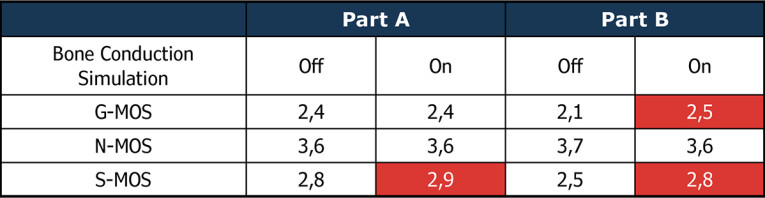
The test results (Table 1 and Table 2) for both devices show a clear improvement in speech quality (S-MOS) with bone conduction sensoring. In both devices, the improved speech detection allows for better control of the noise canceller. The speech signal is less deteriorated, leading to higher speech quality in the presence of background noise. This way, devices with bone conduction sensors can be tested and optimized reliably in the lab to tune the noise canceling algorithms best possible.
Experiment D: Double Talk
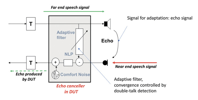
Another improvement with structure-borne sensing can be expected in double-talk situations. In almost any communication device, echo cancellation prevents the far-end listener from hearing the echo produced at the near-end. In general, the echo canceller (Figure 13) is an adaptive filter modeling the echo path and trying to minimize the echo signal by subtracting the inverse echo signal. The echo canceller may diverge if the impairing near-end speech signal is not reliably detected. The adaptation control quality is vital, and the better the echo can be separated from the near-end talker signal, the better the echo cancellation will work in case of double talk. Using the bone conduction signal may improve this separation since it represents solely the near-end speech signal.
Conclusions
Structure-borne sound simulation is crucial when testing modern headsets. Only with the complementing simulation of air-borne and structure-borne sound generated by the human voice can it be possible to evaluate and optimize headsets in different conversational situations comprehensively. aX
References
[1] Recommendation International Telecommunication Union (ITU) ITU-T P.57 (06/21): Artificial Ears
[2] European Telecommunications Standards Institute (ETSI) ETSI TS 103 224: Speech and multimedia Transmission Quality (STQ); A sound field reproduction method for terminal testing including a background noise database
[3] Recommendation ITU-T P.501: Test signals for use in telephony and other speech-based applications
[4] HEAD acoustics datasheet: 3PASS
[5] HEAD acoustics datasheet: 3QUEST
[6] European Telecommunications Standards Institute (ETSI) ETSI TS 103 281: Speech and multimedia Transmission Quality (STQ); Speech quality in the presence of background noise: Objective test methods for super-wideband and fullband terminals
This article was originally published in audioXpress, January 2023
 About the Author
Hans W. Gierlich started his professional career in 1983 at the Institute for Communication Engineering at RWTH, Aachen. In February 1988, he received a Ph.D. in electrical engineering. In 1989, Hans joined HEAD acoustics GmbH in Aachen as vice-president. Since 1999, he has been head of the HEAD acoustics Telecom Division and in 2014, he was appointed to the board of directors. Hans is mainly involved in acoustics, speech signal processing and its perceptual effects, QOS and QOE topics, measurement technology, and speech transmission and audio quality. He is active in various standardization bodies such as ITU-T, 3GPP, GCF, IEEE, TIA, CTIA, DKE, and VDA. He is vice chair of the European Telecommunications Standards Institute (ETSI) Technical Committee for “Speech and Multimedia Transmission Quality” and was chair from 2016–2020. In 2021 he received an ETSI fellowship award.