A very usable system can be implemented for less than $200. You’ll need three things to get the measurement capabilities that amateurs could only dream of last century—a sound card (hardware), measurement software, and a means of interfacing the device under test (DUT) to the sound card. This month, we’ll start by examining sound card requirements. Since most sound cards are intended for gamers, home theater, and musicians, we need to decide what features to look for in a sound card targeted for audio measurement.
Inputs
Musicians like lots of inputs with lots of volume controls. But, you don’t generally need them, and it is one more way to get levels wrong. A bare-bones two-input sound card is ideal. The mike preamps built into some of these units could potentially be useful for low-level measurement, but in the few I’ve tried, the circuitry was mystery meat and greatly limited the distortion and noise performance.
You want line-level inputs (i.e., 10-to-20-kΩ input impedance and 1 to 4 VRMS, full scale). Balanced inputs and outputs are a major plus for measurement. They give you the most flexibility in the sorts of things you can easily measure and provide more options for grounding to achieve the lowest measurement noise. Balanced inputs will reject common-mode noise, and can also be run single ended, if appropriate for a measurement.
The most commonly used input and output connectors are XLRs (pretty universal in pro recording) and 0.25” phone jacks (which are popular in semi-pro and amateur music production). Some units even have combo jacks that can accept both. RCA phono jacks for analog I/O are a sure sign that the inputs and outputs are single ended. Likewise mini-phone plugs. You can still work with those, but it’s unnecessarily limiting and noise can easily contaminate the measurements.
Sample Rates
This will determine the high-frequency limits of your measurements. The Nyquist theorem shows the maximum frequency that can be accurately sampled, known as the “Nyquist limit,” it is half of the sampling frequency. (Historically, this work is attributed to both Harry Nyquist and Claude Shannon, but for whatever reason, Nyquist’s name seems to dominate. My non-mention of Shannon is for convenience and consistency, and is not meant to slight this brilliant mathematician, who was also a singular pioneer of modern information theory.)
Generally, there are filters in A/D converters to limit the input frequency to below the Nyquist limit, but these filters are not perfect brick walls, passing all data below the Nyquist limit and blocking all data above the Nyquist limit. So as a practical matter, the highest measurable frequency will be somewhat lower than the Nyquist limit. As a rule of thumb, I assume that I can’t trust anything above 90% of the Nyquist limit (e.g., for a 192-kHz sample rate, the Nyquist limit is 96 kHz, so I can use the measurement up to about 87 to 88 kHz).
All things being equal, higher sample rates are better. The bare minimum is 96 kHz for any serious measurement — 192 kHz is sufficient for testing most equipment within the audio band. There seems to be very little push for sample rates higher than 192 kHz in the music recording market, so we’re probably limited to that for the foreseeable future. And even that sample rate is the exception, since 96 kHz seems to have become a de facto “hi-res” standard, with 192-kHz sound cards quickly vanishing from dealer stock.
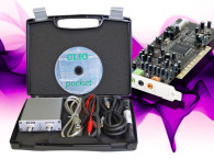
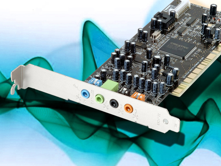
The two sound cards I use in my day-to-day work are an internal (PCI) card, the M-Audio Delta Audiophile 192, with two-channel balanced I/O and 24-bit/192-kHz capability; and an external card, the Echo Audiofire 2, with two-channel balanced I/O and 24-bit/96-kHz capability, communicating to my laptop via Firewire (IEEE-1394 interface standard).
Both use 0.25” stereo phone plugs for each channel. In terms of input and output levels, 0 dBFS (fullscale level) = 4 dBU (1.25 VRMS) for the Echo, and 0 dBFS = 14 dBu (3.9 VRMS) for the M-Audio. If you can afford the price, the Lynx L22 has amazing performance, with a 200-kHz sample rate, distortion, and noise in the single-digit parts-per-million range, and is available in the low-profile PCIe format.
For an external card, the Focusrite Scarlett 2i2 is one I’ve used a few times with good results. As with most other USB interfaces, its maximum sample rate is 96 kHz, but the distortion and the noise performance of the unit I tried was excellent. Current availability of these specific models is spotty, but there are several similar units filling their niches, and I’ll be reviewing some good ones over the next few months.
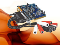
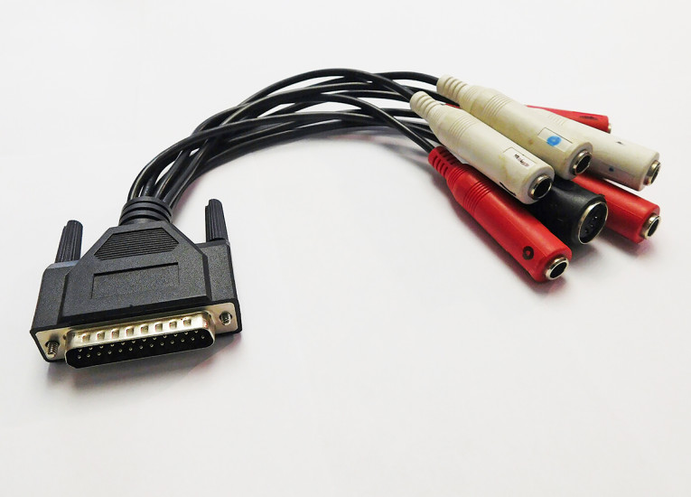
One nice-to-have feature is I/O via a breakout cable rather than the jacks built into the unit (see Photo 1). This reduces issues of strain relief with long cables and as a bonus, enables you to change the type of connector by clipping off the old jacks and soldering on new ones. That’s somewhat tougher to do with jacks directly soldered to a PCB. It can be helpful to use a marker of a contrasting color to label the jacks, especially for those of us with old eyes or the inevitable poor lighting behind the computer.
Limitations
With all of this wonderful measurement power (literally) at our fingertips, there is a great temptation to think that there’s no more need for “conventional” test equipment. Sadly, this is not the case because there are limitations with soundcard-based measurements.
First and foremost, there is the bandwidth. As previously mentioned, the high-frequency limit of a computerized test system is determined by the Nyquist frequency. So if a circuit oscillates at 20 MHz (which is not an uncommon occurrence), it will be invisible to you. Likewise, if you want to measure the residual AC on the output of a switching supply or a Class-D amp, the harmonic content of a jagged 30-kHz waveform, or the quality of an SPDIF signal, you’re out of luck. If you want to look at the rise of distortion in an amplifier with increasing frequency (which is common due to falling open loop gain), the harmonics above the second order for a 20-kHz signal will not be detectable with a 96-kHz sound card, nor will harmonics above the fourth order be detectable with a 192-kHz sound card.
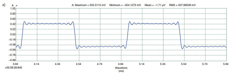
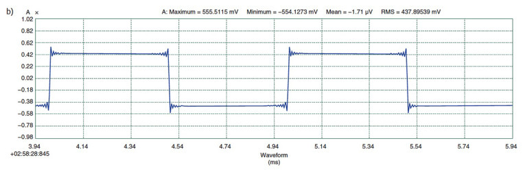
The other consequence of limited high-frequency bandwidth is that clean square waves can’t be generated at midrange and treble frequencies. Square waves have an infinite number of odd order harmonics. Truncation past some upper frequency limit results in a waveform with ringing (the infamous Gibbs Phenomenon). The bandwidth limiting at one-half the sampling frequency necessary to satisfy the Nyquist criterion will slow the rise time and cause ringing (see Figure 1).
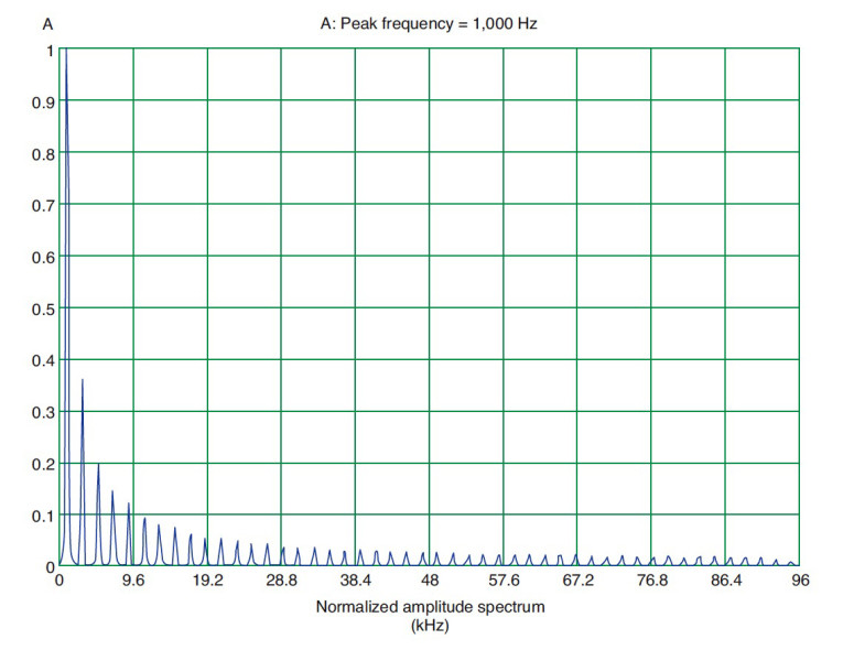
Besides the ringing due to bandwidth limiting, these diagrams also show the effect of sample rate: higher sample rates have a sharper overshoot but of lower magnitude. The frequency spectrum of a sampled square wave is shown in Figure 2. All the harmonics are present up to the Nyquist cutoff. We’re just limited by the basic mathematics, which demand infinite bandwidth and that’s the unfixable cause of the ringing.
So using square waves to check amplifier stability will best be left to conventional instruments (e.g., square wave generators and oscilloscopes), despite the temptations of the digital oscilloscopes and square wave generators built into the measurement software.
At the other end of the frequency range, the inputs and outputs of sound cards are AC coupled, so DC and very low frequency measurements (e.g., measurement of bias drift over time and dielectric absorption of capacitors) can’t be done without building some elaborate chopper-type interface. A good sound card can go well below subwoofer rolloff frequencies and should even be able to measure phono cartridge-tone arm resonance frequencies (7 to 12 Hz, optimally).
Second, there is impedance. A sound card’s input impedance is likely to be somewhere around 10 kΩ. That’s no problem if you’re measuring things such as preamps with low output impedances or power supply outputs, but if you want to measure a high-impedance source (e.g., the signal at the plate of a tube or drain of a FET), the sound card will load it down. However, this issue can be easily remedied.
Third, audio signals range from microvolts to hundreds of volts, whereas sound cards have their “sweet spot” for top performance in the 1-to-2-V range. If, for example, the input signal for a distortion measurement is too low, it will be difficult to pick up the harmonics in the noise. If a signal is too large, measured distortion will be high because of the sound card’s input stage overloading. If the signal is large enough, it can even damage the sound card inputs. As with impedance, this is also easily taken care of, as we will see later in this article series.
Fourth, you need to be able to check your work. There are so many moving parts that odd-looking measurements need to be verified. You may find that you’ll want to do this as a matter of course. Seeing a lot of high-level high harmonics in a sine wave measurement or a funky frequency response? They may be there, but it could also be that something is clipping or there’s a wrong setting or a multitude of other reasons. An analog oscilloscope will provide a useful check. Likewise, unusual noise—is it a grounding issue or a pickup from some radiating device?
Fifth, the distortion spectrum vs. level may be suggestive, but using an oscilloscope to examine the output of the distortion residual from a conventional distortion analyzer will be faster and more certain. Of course, you can multiply your measuring power by running the output of the distortion analyzer into the sound card measurement system, allowing it to be monitored in the time domain (i.e., virtual oscilloscope) or the frequency domain (i.e., spectrum analyzer).
Comparing the distortion waveform with the input waveform can provide clues as to the distortion source by noting the point(s) on the waveform where the distortion occurs. For example, if there’s a spike in the distortion waveform that lines up with the input signal’s zero crossing, you’re probably dealing with crossover distortion.
Bottom Line
The virtual Swiss Army knife of a good soundcard-based system will take care of the vast majority of your needs, but every once in a while you have to reach into your metaphorical toolbox and pull out a tape measure or a monkey wrench. The big tools will always have their uses. And the naked sound card will need to be clothed to take advantage of its versatility and performance. Fortunately, that part is easy.
In the next article, we’ll look at computers and some measurement software options. ax
Resources
“Gibbs Phenomenon,” Wikipedia, http://en.wikipedia.org/wiki/Gibbs_phenomenon
“Shannon-Nyquist Sampling Theorem,” Wikipedia, http://en.wikipedia.org/wiki/Nyquist–Shannon_sampling_theorem
Sources
Audiofire 2 - Echo Digital Audio Corp. | www.echoaudio.com
Scarlett 2i2 audio interface - Focusrite, plc | http://us.focusrite.com/usb-audio-interfaces/scarlett-2i2
Lynx L22 PCI sound card - Lynx Studio Technology, Inc. | www.lynxstudio.com
Delta Audiophile 192 audio card - M-Audio | www.m-audio.com
This article was originally published in audioXpress, July 2015.
Read Part 1