Several things have, in my view, driven this expansion, including:
• the increasing display of sophisticated measurements in magazine and blog equipment reviews
• the increasing familiarity of audiophiles with computer processing of audio signals
• the increasing use of room measurement and correction software built into audio components
• the increasing availability of free and easy-to-use measurement software for free-standing measurement
Regarding the last point, the most popular choice is typically Room Equalization Wizard (REW), a freeware package that has taken the audio enthusiast world by storm. As its name implies, REW is mostly targeted toward room measurement and correction, but under that exterior is a very powerful and versatile measurement package that audio enthusiasts have been using for frequency response and distortion measurements. It also has the nice feature of being able to automatically generate filter parameters for room correction after doing acoustic measurements. The progress in this software and its applications since my first article on software options has been impressive, and the support that REW gives users through several Internet audio forums is noteworthy.
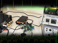
For perhaps the majority of users and measurements needs, a simple sound card and REW will do the job nicely. This is especially true with the latest generation of USB microphones that do not require phantom power. But for more sophisticated measurements, more sophisticated tools are needed, and there’s been a lot of progress in this area. In this article, I’m exploring the Linear Audio Autoranger Mk II, a hardware product that could improve the measurement capabilities in small labs. In a forthcoming article, I will discuss a software product that will also improve measurement capabilities, the latest version of Virtins Multi-Instrument.
The Autoranger Mk II
Sound cards have several limitations when you want to measure voltages. Most notably, they have a limited range of input voltages so that if, for example, you want to measure the output of a power amp, you will quickly exceed the maximum input voltage limitation. This requires rigging up an external attenuator, and for best performance, you’ll need several of them to translate the amplifier’s output through a sweep to full power to the roughly 1 V to 2 V that is in the optimum performance range for most sound cards. And of course, sound card systems need to be calibrated for each attenuator used, as well as having to be redone any time a volume control is changed.
Another potential issue is the need for both balanced and single-ended inputs and outputs for the measurement and the stimulus, respectively. While this is generally available on pro-sumer recording interfaces, it’s not universal, and most USB cards intended for gaming or home theater and PCIe solutions are single ended only. Even rarer is any sound card or recording interface that allows inputs to be floated, either to break up ground loops or to measure signals in the presence of DC.
This is something I discussed in Part 4 of my earlier series on sound card measurement (audioXpress, September 2015). To overcome these limitations, I ended up using the excellent measurement interface box from my buddy Pete Millett (see Resources); this product is a measurement interface box that goes between the device under test (DUT) and the sound card.
As described in my article and the write-up on Millett’s website, the Millett box provides manually switched attenuation of 1, 10, 100, and 1000 (or 0 dB, -20 dB, -40 dB, and -60 dB). It also has balanced and unbalanced inputs and outputs that can be floated, with as much as a 200 VDC offset. Additionally, its 100 kΩ input impedance is about 5 to 10 times higher than that of typical sound card inputs, so it will tend to have less effect on a high impedance circuit measurement. Conveniently, the Millett box also has a built in AC voltmeter, which can be useful for both calibration and basic measurement.
A new sound card measurement interface option for audio measurement first appeared about two years ago, the Autoranger, designed and sold by audioXpress’ Technical Editor Jan Didden through his Linear Audio website. This interface performs a similar task as the Millett box, but is significantly more versatile. Like the Millett box, the Autoranger was available as a kit or fully assembled. I got an early version of the Autoranger and gave Didden feedback on usability and performance.
In response to the feedback from many other early adopters, the design was recently updated to the Autoranger Mk II, with lower distortion and noise than the original unit. I installed the new Mk II boards for evaluation. As its name implies, the Autoranger Mk II will automatically adjust input gain to scale the input signal to provide a nominally 0.4 V or 1 V signal (user selectable) to the sound card. In the case of the Autoranger Mk II, the voltage gain varies from +18 dB to -42 dB in 6 dB steps, which provides great flexibility regarding getting the measured signal close to the optimum range for the sound card. The user also has the option of switching the gain range manually.
The Autoranger Mk II is housed in a rather generic powder-coated steel case, with silk-screened legends. There is a CE designation on the back. Also on its back is a USB plug for power, which can either be provided by a computer, a plug-in USB charger, or a 5 V portable battery power bank. The allowable power input voltage range is 3 V to 10 V. No matter which power option is used, the signal circuitry is isolated by the internal switching power supply, Didden’s SilentSwitcher, which is also available as a standalone module for other projects (see Resources).
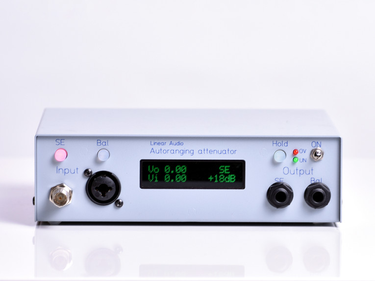
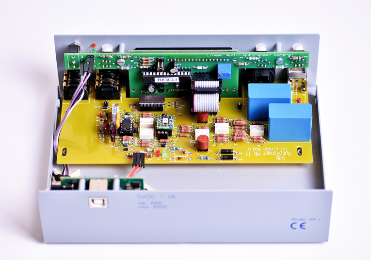
The very low noise and isolation provided by the SilentSwitcher is integral to the Autoranger Mk II’s noise and distortion performance. The front panel has two input jacks, a BNC for single-ended sources, and a combination XLR/TRS for balanced sources (see Photo 1). The user can select between them with a button push. Helpfully, the button for the chosen input illuminates to indicate that it’s active. Outputs are separate for single-ended or balanced sources, and are each a TRS jack.
The large LED display indicates the measured input RMS voltage, the output voltage to the sound card, the gain, and input configuration (balanced or single-ended). By moving internal jumpers, the user can select the display color (red, green, or blue) and adjust brightness. Contrast is adjusted via an internal trimmer. The voltage measurement capability is particularly useful for calibrating the sound card in whatever measurement software is being used.
Internally, three PCBs contain the SilentSwitcher power supply, the display electronics and logic, and the analog signal circuits (see Photo 2). No doubt someone could put all of this in a surface-mount package to reduce the interface size and make a slicker package, but for its intended bench use and for the convenience of people who want to build this from a kit, the use of larger through-hole components and a standard metal case doesn’t present a huge disadvantage.
To switch between Automatic and Manual gain adjustment, the user goes through a multiple button press sequence—first, the Hold button freezes the gain range at whatever value it is at the time of that button push, then the gain range can be manually incremented up and down in 6 dB steps by pressing the Bal or SE buttons, respectively. Helpfully, there are two LEDs on the front panel to indicate under-range and over-range, so you can get a visual indication of whether the manually chosen range is appropriate for your measurement.
One important limitation: the Autoranger Mk II’s input impedance is either 10 kΩ or 20 kΩ (which is specified when the unit is ordered). That will present no difficulty for modern sources (e.g., DACs, preamps, power amps) but precludes the use of the Autoranger Mk II in measuring internal voltages at high impedance points or measuring older tube equipment, which would be excessively loaded down by the Autoranger Mk II. As far as I can see, there’s no disadvantage to using the 20 kΩ impedance version, so that’s what I’d recommend.
According to Didden, raising the input impedance makes it much more difficult to design the attenuator for flat response and low noise. The world is still awaiting my dream, an interface with a 1M input impedance that can be used with oscilloscope probes. Besides the lower loading from the higher impedance, the ability to use scope probes allows a 10x option, increasing the input voltage range and drastically reducing the effect of the probe’s cable capacitance on the circuit being measured. This would especially be a blessing for those of us who work with vacuum tube and field-effect transistor (FET) circuits.
Measurements
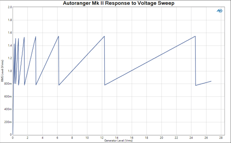
The test setup here varied between an Audio Precision APx525 and an APx555 B Series, with the latter used for distortion measurements. I first connected the Autoranger Mk II via balanced in and out, with the nominal output setting at 1V. The AP was then set to step a 1 kHz sine wave from 1 mV to its maximum output voltage (26.6 V) while monitoring the Autoranger Mk II’s output.
This measurement is shown in Figure 1, and it can be seen that the Autoranger Mk II switches ranges when its output voltage reaches about 1.55 V, with the next range being 6 dB (or 2x) lower at 0.775 V. At the lower voltage ranges, the graph shows a lower transition voltage, but this is a measurement artifact resulting from the finite voltage step size in the applied voltage sweep. Other than this measurement anomaly, the transitions are all quite consistent. I note, however, that these threshold voltages for switching are significantly higher than the numbers given in the User Manual, though for most sound cards, this should not be a concern. For the nominal output setting of 0.4 V, the outputs ranged from 350 mV to 660 mV, again higher than the numbers given in the User Manual.
It would be nice to see the documentation updated for the Autoranger Mk II version. One thing I noticed was that if I made the sweep slow enough, I could get the Autoranger Mk II to act a bit chaotically near the switching transition. Admittedly, this took some effort and is not indicative of normal use, but perhaps a bit more hysteresis in the transition could eliminate this behavior entirely.

The frequency response of the Autoranger Mk II in-balanced out mode is shown in Figure 2. On the low end, it starts rolling off at 20 Hz, where it’s about -0.3 dB. On the high end, it is absolutely flat to the 80 kHz limit of the AP’s sine wave generator. The claimed high-frequency limit is 600 kHz, and I see no reason to doubt that.
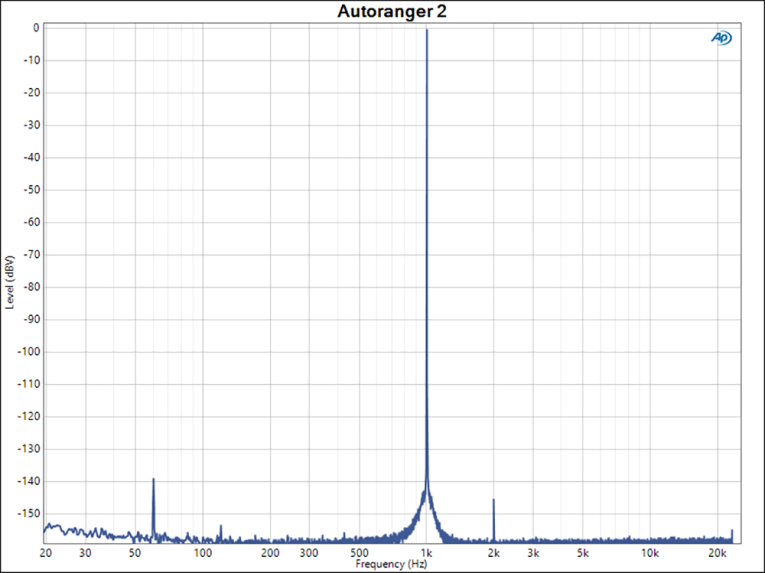
Figure 3 shows the 1 kHz distortion at unity gain. The only distortion component visible is the second harmonic at -145 dB, which is less than 0.000006%! There’s a very small amount of 60 Hz pickup, which may have been from my cabling, but at -140 dBV (125 nV), I didn’t spend much effort in tracing it down. This is superb performance which challenges even the APx555 B Series, and the fact that any of these distortion products can be seen suggests that the noise of this unit is not the measurement limitation.
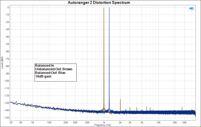
Switching to 18 dB gain, I compared the spectra from both balanced and single-ended outputs (see Figure 4). For these measurements, I displaced the frequencies slightly to make differences on the graph more visible but not otherwise affect the measurement.
The only significant differences are the visible even-order harmonics in the single-ended outputs, most notably the second harmonic at -124 dB (0.00006%). This is unsurprising since symmetric circuits tend to cancel even-order harmonics, and the single-ended output is not symmetric by definition. Nonetheless, this is a superbly low distortion result, and is better than most signal sources and analyzers. There’s no hum visible in either measurement, so I inadvertently did a better job of cabling than during the test run of Figure 3.

Increasing the frequency to 5 kHz gives the results shown in Figure 5. The second harmonic for the balanced out has risen a bit, but the other distortion components seem to be basically unchanged. There’s a spurious 1 kHz pickup in the single-ended results, which I see from time to time in low-level measurements— I believe that it’s a pickup from a nearby USB cable, but it is a nice illustration of the inherent common-mode noise rejection of balanced circuits.
Speaking of which, Figure 6 shows the response to a 1 V common mode input signal with the Autoranger Mk II set to 0 dB and 18 dB of gain. This was measured both at the single-ended and balanced outputs. The balanced output curves show a minimum of common mode response (maximum of common mode rejection) at about 1.8 kHz, with common mode rejection (CMR) deteriorating above and below that frequency.
Not surprisingly, they differ by about 18 dB through most of their range, indicating that the limitation on CMR is in the input stage. Minima for the output at 0 and 18 dB gain are at -82 dB and -67 dB, respectively. The common mode responses measured at the single ended outputs are higher (lower CMR) at about -38 dB, and flatter with frequency, which may be a clue about the source of the CMR limits for that topology.

Concluding Thoughts
It’s been interesting to see the evolution of this product over the past few years. The distortion and noise results show that a lot of attention was paid to the details of the circuit and implementation, and it is unlikely that the Autoranger Mk II would be the bottleneck in any sound card-based measurement system.
On the contrary, this product enables users with high-quality sound cards or recording interfaces to perform measurements to the level that is usually reserved for extremely expensive professional-grade audio analyzers. Indeed, its performance required the use of the newest and most elaborate Audio Precision system to characterize, and it greatly exceeded the performance of the APx525 I use day-to-day in my lab.
The Autoranger Mk II is also easy and intuitive to use, and reconfiguring it is rapid and convenient. The only remaining limitation is still input impedance — the Autoranger Mk II is more than suitable for measuring equipment, but getting measurements at the circuit level remains an unconquered challenge.
Although the Autoranger Mk II gets closer to the ideal measurement interface than any previous products, the world still awaits an interface with the same input characteristics as oscilloscopes and the ability to use 10x probes.
In an upcoming article, I’ll combine the Autoranger Mk II with a high-performance recording interface and the latest version of Virtins Multi Instrument to demonstrate near state-of-the-art measurement capability and flexibility. aX
This article was originally published in audioxpress, April 2020.
Resources
J. Didden, “The L|A Autoranger,” www.linearaudio.nl/la-autoranger and www.youtube.com/watch?v=K4TRhEjaIcs
J. Didden, “The SilentSwitcher,” www.linearaudio.nl/silentswitcher
P. Millett, “Sound Card Interface” www.pmillett.com/ATEST.htm
S. Yaniger, “Sound Cards for Data Acquisition in Audio, Part 4” audioXpress, September 2015
Sources
REW software
Room EQ Wizard | www.roomeqwizard.com
Virtins Multi Instrument software
Virtins Technology | www.virtins.com/multi-instrument