The AX5689 is an eight-channel audio amplifier controller IC with digital inputs and CMOS level PWM outputs, enabling high-order digital control loops with post-filter feedback. This article reviews the reference design board using GaN Systems output devices, configured as a two 500W channel BTL (2Ω) at 50V.

An apocryphal story about Alexander the Great says that, upon surveying his domain, he wept because he had no more worlds to conquer. Every time I test a new piece of audio electronics, the same thought crosses my mind — Audio engineers seem to have conquered all of the traditional limitations and problems of the earlier generations of equipment in the electronics chain, and I imagine that, paradoxically, this can in itself be a bit of a frustration. “Have I innovated myself out of a job?”
Perhaps this is nowhere more evident than for power amplification, where distortion has been banished to the nearly unmeasurable, source impedances are smaller than the resistance of binding posts, massive amounts of power (almost unthinkable at the beginning of the 21st century) are available in tiny and cool-running packages, and prices have plummeted. We’ve also hit asymptotic limits on efficiency, well surpassing the “80” part of Pareto’s 80:20 rule.
It appears the principal differentiators among modern amps are packaging, features, and price. Likewise, amplification for OEM products (e.g., active speakers) has even less room to grow and improve since there’s no consumer-facing packaging. Could there be any new approaches left that bring tangible advantages to the table?
The Technology
Enter Axign’s new Class-D amplifier controller chips. Axign is a Netherlands-based fabless chip supplier. Its new PWM Class-D controllers are supplied in two types: the AX5688 for two-channel bridge-tied load (BTL) output configuration and the AX5689 configured for a four-channel BTL. The outputs are pulse-width modulation (PWM) at CMOS level to drive the output stage driver circuits. So far, all conventional. But looking more closely, the Axign chips have some very novel elements.
A block diagram of a system using the Axign controller is shown in Figure 1. First, unlike conventional Class-D controllers, the inputs are natively digital, nothing within the chip (with one exception — a group of ADCs, which we will discuss a little later in this article) is analog until the output. The chip’s input is addressed via the usual I2S protocol. The open loop gain versus frequency is also implemented digitally, allowing a high open loop gain, with a fifth-order roll-off. This configuration allows the distortion to be consistent across the audio band, but also leads to high suppression of the carrier.
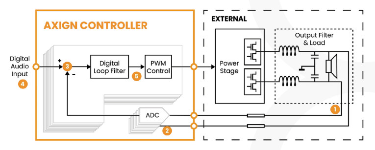
So, you might wonder how feedback is done, since that usually involves taking the difference between input and a fraction of the output signal, usually an analog task. The answer involves another interesting innovation — digital feedback.
This technique was described in a series of papers and patents from Daniel Schinkel and Fred Mostert (see Resources). Instead of a conventional feedback loop, the differential-mode amplifier output is digitized by a high-speed low latency Delta Sigma (ΔΣ) ADC, then input and output are subtracted in the digital domain.
Why hasn’t this conceptually simple approach been done before? This path is not an easy one. The ADC is required to have high bandwidth and low latency for stability. ΔΣ ADCs can have issues with high quantization noise. Digitally filtering it introduces latency and phase shift, which complicate stability. So, almost on-theme here, the ADC derives feedback via a DAC that has a low-pass filter function. This allows compensation for digital filtering and greatly reduced noise in the audio band. In the implementation tested here, the sampling is done every 20ns, which is more than fast enough to achieve a stable control loop well beyond the audible range. In the Axign chip, the ADCs are doubled up to get a 3dB increase in signal-to-noise. Surprisingly, there is no dissipation penalty for the ADCs. Axign’s design reduces their power use to 15mW each.
The output drive is configured for multiphase, which greatly reduces electromagnetic interference (EMI) and demands on the output filters, and the feedback is taken following the output filters. It’s well known that nonlinearities in output inductors are often the limiting factor for Class-D amplifier performance. This can be overcome at significant money, space, and heat costs with inductor design, but even more effectively with post-filter feedback. I’ve seen this used in several other premium Class-D amplifiers (e.g., Orchard, Hypex, Purifi), but in combination with multiphase drive, efficiencies, and performance can be maximized at low cost.
Speaking of efficiency, the demo board uses GaN output devices. As I’ve discussed in a couple other articles, GaN brings a lot of benefits, specifically from the higher charge carrier mobility and thus lower channel resistance. In theory, one can achieve higher switching speeds with GaN compared to silicon, but this goes well past the point of diminishing returns. Where GaN really shines is exploiting the low resistance (and thus low I2R heating) to drive very low impedance loads.
For active speaker use (a key target for the Axign chips), efficiency is particularly important since the amp will most often be built inside a box without particularly good thermal flow. Of course, at high powers, efficiency is high because of Class D (and the use of GaN output devices), but realistically most operation is done at lower powers, where Class D has far less of an efficiency advantage. Any amp has what I call a “power overhead,” that is, the power needed to light the lights, run the logic and input stages, and of course any ADC or DAC. So as a practical matter, the highly touted Class-D efficiency advantage is honored more in the breach.
Axign prioritized efficiency at lower power by at least two means. First, the low power consumption of the ADCs; and second, through the use of a novel PWM scheme, which takes advantage of the differential outputs and modulates the common-mode voltage. This also greatly reduces the stress and dissipation of the inductors used in the output filters. Because of the low power consumption resulting from the design, the dissipation of the amps at idle and low power is under 1.5W per channel, enabling low heat output and higher reliability in active speaker use. Of course, at high power, the Class-D advantages dominate, and the use of low on-resistance GaN output devices further increases the advantage.
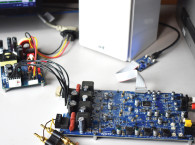
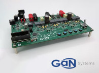
The Axign GaN Demo Board
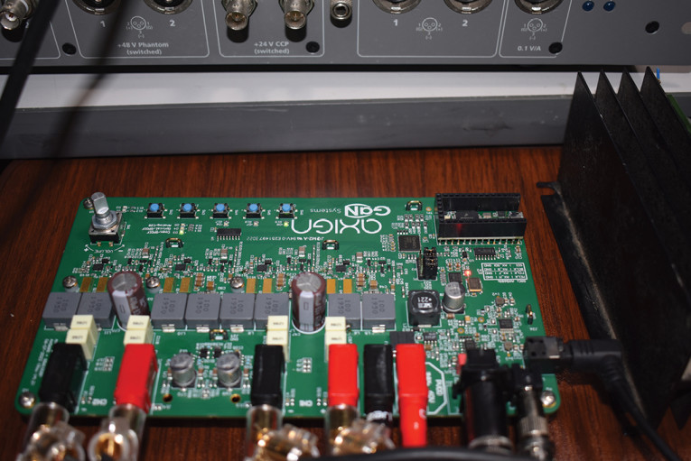
As mentioned, the board (Photo 1) is a collaboration between GaN Systems and Axign—since its release, GaN Systems was acquired by Infineon, so there’s some question about the continuation of the corporate relationship, but the Axign controller chips could be used with other output transistors (e.g., silicon MOSFETs, SiC, other GaN devices) just as easily. So, although details of this particular board may vary a bit for future designs, the basic concept has a lot of flexibility in application.
A block diagram of the demo board is shown in Figure 2. You can see that the provided inputs include SPDIF coaxial and optical, single-ended analog, and I2S. Since the controller is natively digital, the analog inputs go through a buffer and a high-speed ADC at the input before the AX5689S controller. The ADC and buffer are good enough that there’s no measured difference in performance between using analog and digital inputs. Digital inputs are first fed to a high-performance CS8422 sample rate converter where they are resampled and sent to the controller via an I2S bus at 192kHz.
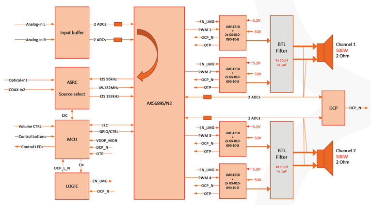
Other controls on the board are managed by a Teensy 3.2 microcontroller, including thermal management, DC offset, PWM controller programming, and sample rate conversion. There’s an optical rotary controller for volume level.
The output stage uses GaN Systems’s GS61008 transistors, which are bottom-cooled. They feature an extremely low 7mΩ on resistance, which is key to the ability to run cool without external heatsinking. The driver chip for the output stage is a Texas Instruments (TI) LMG1210. Of course, other devices and drivers could be used in applications based off the demo board’s reference design.
The demo board requires a power supply of 50V nominal. Because the board includes a power inverter onboard, a single-ended supply is sufficient. I bought a (relatively) inexpensive 48V supply rated at 20A to run the board. Conveniently, the power connections to the board are banana plugs rather than a proprietary connector or (worse yet) screw terminals. The first power-up produced no sparks or smoke, which was a good omen.
Measuring the Axign GaN Demo Board
Measuring modern Class-D amps is usually an exercise in ennui. They are much of a muchness. A pretty excellent muchness, but not a lot of variation. The Axign demo board held a few surprises.
As usual, my test setup comprises an Audio Precision APx525 running the APx software version 6.1. I have a set of 8R and 4R high power dummy loads and a small two-way bookshelf speaker for monitoring. Voltage levels are double-checked with an HP 3466A precision multimeter. Most measurements were taken with the APx525’s built-in AES17 20kHz filter, but it was obviously turned off for the wideband noise measurements.
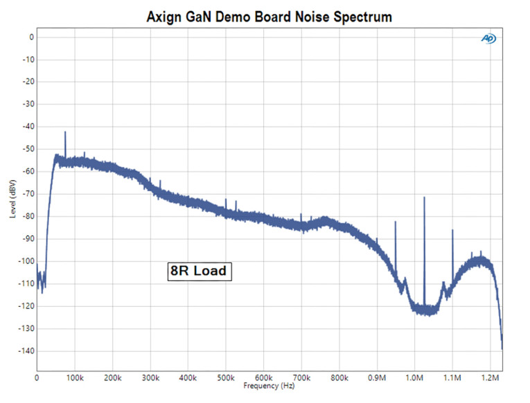
The noise spectrum of the demo board is shown in Figure 3. There are two things of note here. First, one can see the noise-shaping, which removes any issues of audible hiss even with extremely sensitive speakers. The low 1/f corner is icing on the cake. I measured under 140µV in the audio band (20Hz to 20kHz), and the white spectrum means most of even that minuscule amount that lies outside the regions of maximum human acuity. Second... where’s the carrier? Normally, it shows up in the 100mV range for higher-end Class-D amplifiers, which isn’t really an issue, but the outstanding result here speaks to the effectiveness of the multiphase drive and balanced output filtering, as well as taking feedback from the load side of the filter.
Output impedance is one of the most critical performance attributes of a power amplifier. Although humans have relatively low sensitivity to distortion, we can pick up very small deviations in frequency response. Because an amp’s output impedance forms a voltage divider with the load impedance, lower values mean lower frequency response variations with actual speaker loads. There are several ways of performing this measurement. The simplest is to input a signal, measure the output voltage, change the load impedance, and see how the measured voltage changes. The source impedance can then be easily calculated from the voltage divider equations and Kirchoff’s Law. Ideally, this is done at various frequencies across the audio spectrum since the source impedance usually varies with frequency.
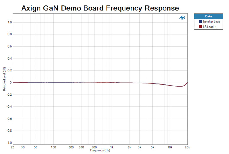
Imagine my surprise when changing the load from 10R to 2R caused NO change in the output voltage! This was true at several spot frequencies (50Hz, 200Hz, 1kHz, 5kHz, 15kHz), and is a remarkable result, predicting that the amp’s sound will remain uncolored even using speakers with wildly swinging impedance. A nice illustration of this is shown in Figure 4, which gives the level relative to 2.83V over the usual 20Hz to 20kHz frequency range for a pure 8Ω resistance and a two-way sealed box bookshelf speaker. Note the highly expanded scale. The amp’s basic frequency response has an inaudibly small 0.08dB dip in the top octave, but there was absolutely no measurable difference using a test resistor and a speaker.
Other than frequency response, primus inter pares for amplifier characteristics is power delivery. Figure 5 and Figure 6 show the demo board’s distortion versus power for two different loads, 8R and 4R, respectively. The distortion knees are at somewhat over 100W and 200W, also respectively, with the 1% distortion point at about 140W and 280W for the two loads. Note that the curves look almost identical but scaled for power by the load resistances. This is suggested by the source impedance measurements, but it’s nice to see that the almost perfect doubling of power going from 8R to 4R loads is maintained even at high power.

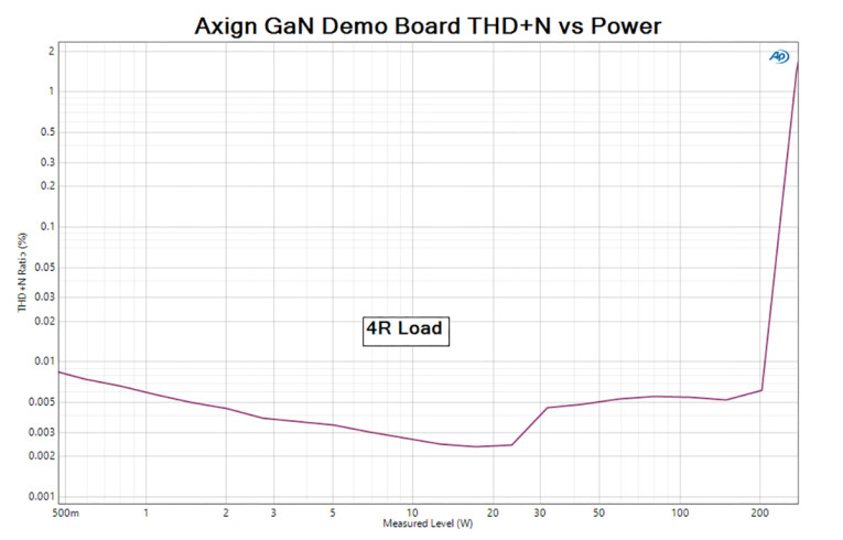
The step in distortion seen at about 12W and 24W for the 8R and 4R measurements is actually a measurement artifact and not an actual distortion increase in the amplifier. The artifact is a result of the previously mentioned common-mode modulation and corresponds to the range changing point of the APx525 analyzer. Of course, this is not an issue for loudspeaker loads, which are driven purely by the differential signal.
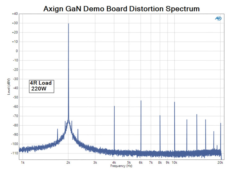
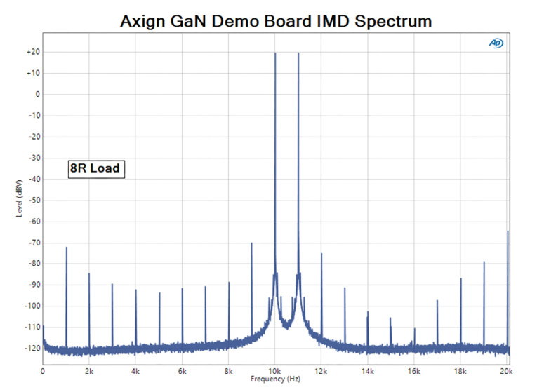
Figure 7 shows the distortion spectrum for a 4R load with 220W. It’s dominated by the third harmonic at about -85dB, but is otherwise unremarkable. Likewise, a pair of 10V signals at 10kHz and 11kHz across an 8R load gives the intermodulation spectrum shown in Figure 8. The largest error is a sideband at -96dB; this is quite an excellent result.
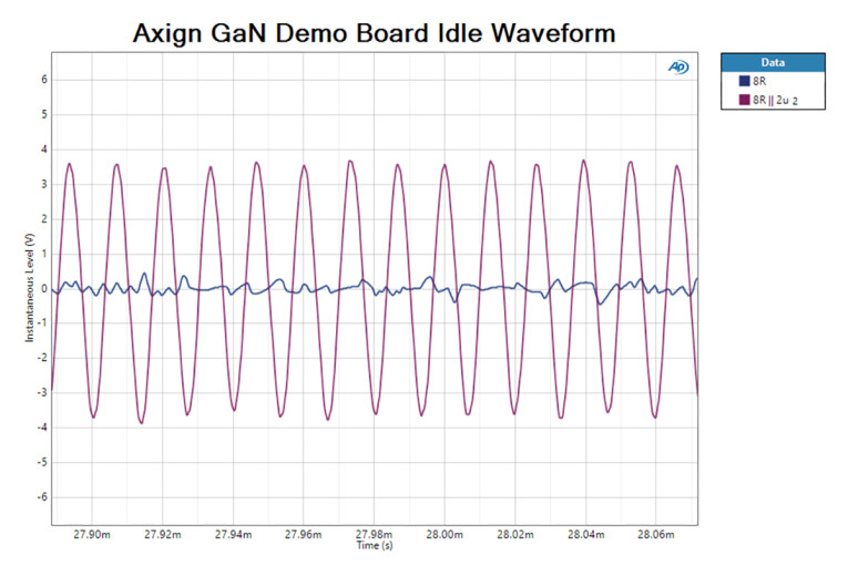
One test that I’ve incorporated into my measurement suite is driving a heavily capacitive load. I used a 2µF capacitor across an 8R load. This is a far larger capacitance than nearly every electrostatic loudspeaker, but there are a very few edge cases which could approach that. The demo board was not at all happy with this load! Figure 9 shows the change in the noise spectrum between the 8R load and the 8R paralleled with the capacitor. Large discrete noise spikes arise (near oscillation) at ultrasonic frequencies and the noise level in the audio band rises sharply.
The idle waveforms (Figure 10) show the oscillatory behavior induced by this extremely difficult load. For the very few ESLs that have this high capacitance, there could be an incompatibility issue, but for the 99.9% of more normal speakers, this is not a factor at all. Certainly, with the ESLs I used for listening tests, this problem did not arise, and I reiterate that this test is meant to be an extreme case and not representative of any dynamic speaker or the majority of ESLs.

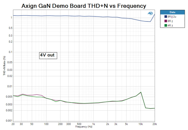
A sweep of distortion versus frequency at 4V out for 8R, 4R, and 8R paralleled with the 2µF capacitor is shown in Figure 11. For the resistive loads, it remains low across the audio band. With the extreme capacitive load, the rise in noise dominates and the result is less good. Nonetheless, with more normal loading, the lack of significant rise at higher frequencies reflects the shaping for the open loop transfer characteristic.
The Axign Demo Board In Use
For the listening portion of the review (my favorite part!), I used the board with two different systems. System 1 has the WiiM Pro streamer as a source, connected via an optical cable, consistent with my view that digital is always more precise and reliable than analog. The Axign amps then drove a pair of Quad 988 electrostatic speakers. For System 2, the Axign board’s input was connected to the preamp output of an NAD M10 streamer/integrated at the Axign’s analog inputs to drive the upper section of a modified and biamped pair of NHT 3.3 dynamic speakers. The change in source when switching between these two systems was because the WiiM Pro’s analog outputs have mediocre performance (this has been claimed to be corrected in the newest version, the WiiM Pro Plus) and because I use the Dirac feature of the M10 with the dynamic speakers but not the ESLs.
Not unexpectedly, the Axign amps functioned flawlessly. There were no turn-on or turn-off pops or noises, the speakers were absolutely silent until the music played, and everything was tight, stable, and audibly in control. The low source impedance ensured that there was no tonal coloration. Whether I played the delightful “Sandman” from Count Basie’s Kansas City 3 on the always-reliable Pablo label, “Funny Ways” from the superb Steven Wilson remaster of Gentle Giant’s eponymous debut album, my homemade recording of Lee Barber’s “All Night Long,” or heavier rockers like Dream Theater’s “This Dying Soul” from their Train of Thought album on Elektra, the sound was always clear, clean, uncolored, and unstressed.
Swapping the Axign board back and forth with the Nilai DIY amps currently in my system, the sound remained unchanged — a high compliment! Obviously, the Axign ran out of gas before the more powerful Nilai on heavy metal turned up to 11, but recovery from clipping was totally without drama.
Also, a high compliment: During the hot and humid summer here in rural New York, the amp put essentially no heat into the room. I couldn’t get the board anywhere near hot even with extended high-power testing.
My only regret is that I didn’t have one of those idiosyncratic boutique speakers with really wild impedance dips to show off the low impedance drive capability, but I would have no hesitation pairing a design like this with one of those oddities. And of course, for active speaker use, this would be a non-issue.
Conclusion
The Axign chips used in a reference design deliver good distortion performance, very low noise, excellent carrier suppression, exceptionally low source impedance and drive capability, and thus absolutely no coloration to the sound. It took major effort to make the amplifier misbehave. All this while running absolutely cool with no external heatsinking! The demo board reference design shows the sort of performance possible for amplification integrated into active speakers or for a stand-alone amplifier using the remarkably versatile and efficient Axign controller chips. There’s a lot of innovation packed into a few square centimeters. aX
Author Acknowledgements: I thank Axign and Richard Langezaal for the use of their diagrams as well as patient explanations, and Dimitri Danyuk from Harman for giving me background and user feedback.
Resources
W. Maas, “Axign of Things to Come,” audioXpress, December 2017.
F. Mostert et al., “A 5×80W 0.004% THD+N Automotive Multiphase, Class-D Audio Amplifier with Integrated Low-Latency ΔΣ ADCs for Digitized Feedback after the Output Filter,” Session 5, Analog Techniques, 5.1, Institute of Electrical and Electronics Engineers (IEEE), 2017, https://ieeexplore.ieee.org/document/7870273
Daniel Schinkel et al., “A Multiphase Class-D Automotive Audio Amplifier with Integrated Low-Latency ADCs for Digitized Feedback After the Output Filter,” IEEE Journal of Solid-State Circuits, Volume 52, No. 12, December 2017.
S. Yaniger, “GaN Technology in Audio Power Amplification,” audioXpress, April 2022.
This article was originally published in audioXpress, December 2023