
The high-level idea of an active noise-cancelling (ANC) system is quite simple. The goal is to eliminate unwanted sounds such as airplane noise, highway noise, or people’s chatter. Several techniques achieve this. First, it is essential to recognize passive cancellation. A common ANC device form factor that exemplifies this are the true wireless stereo (TWS) earbuds. The dominant design solution is a rubber ear tip that fits the ear canal tightly. When inserted into the ear, the device acts somewhat like an earplug. It provides low-pass acoustic filtering and significantly attenuates high-pitch sounds without any electronics involved.
The feed-forward (FF) ANC path is a second noise cancellation technique. In this technique, an external microphone picks up the unwanted environmental sound. The signal is inverted to create anti-noise and is played by the speaker. The ambition is to create perfect cancellation inside the ear. The FF signal is an exact inverted copy of the sound naturally coupling into the ear from the outside. FF ANC is usually effective in the low- to mid-band range.
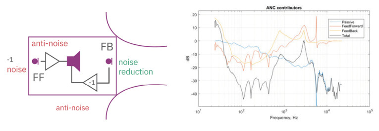
The feedback (FB) ANC path is the third technique: The microphone inside the ear monitors the sound. The microphone’s output is inverted and played back through the speaker. This way, the noise level inside the ear is reduced. FB ANC cancellation is effective in the low-frequency range. A typical example is shown in Figure 1.
Feed-Forward ANC
A concept block diagram of the FF system is given in Figure 2. The passive transfer function is a low-pass filter, subject to the mechanical design of the headset and the way it fits in the ear. Active transfer function includes a microphone, digital signal processing (DSP), and the transfer function of the speaker generating sound in the ear canal.
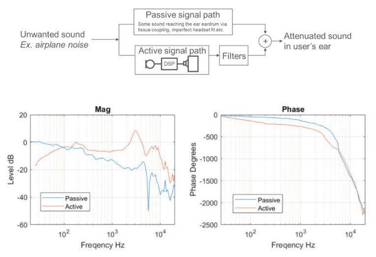
The shape of the active transfer function consists of these expected features: second-order high-pass effect in the low end from microphone and speaker low-frequency roll-off (LFRO). There is a pinna resonance from the speaker transfer function at higher frequencies.
Note that the phase response of the active path includes linear phase contribution from digital microphone ASIC latency and DSP processing latency. The idea is to pick the ANC filters to achieve complete cancellation so that active and passive signals are equal in magnitude and perfectly out of phase at every frequency. ANC filters are part of the DSP block, but it is convenient to separate those from the fixed components of the active transfer function.
The next step is to set the ANC filters in the active signal path. How accurately must the active and passive paths be matched to make ANC noticeable to the consumer? Both magnitude and phase differences will lead to less cancellation. Figure 3 illustrates this.
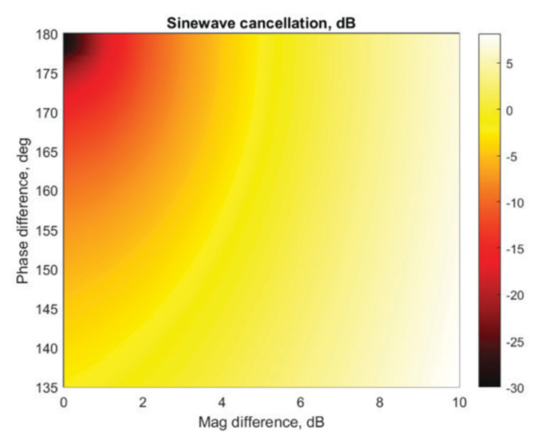
Let’s pick -10dB cancellation as a clearly audible target. Cancellation is perfect in the ideal case with a 0dB magnitude difference and 180° phase shift. However, a -10dB or better noise reduction target is achieved with a magnitude mismatch of up to 2dB and phase deviation from the ideal of 180° up to 20°. This exercise shows how accurately the ANC filters need to be set.
Having measured the passive and active transfer functions without ANC filters (unity filters), it is now possible to compute the target ANC filter curves for magnitude and phase. The curves are shown in blue in Figure 4. Unfortunately, this exact shape cannot be reproduced with available DSP filters in the ANC chip. Commonly there is a cascade of configurable second-order IIR bi-quad filters available. Also, there is a fundamental difference: The target phase response is rising in the frequency range of interest. A perfect fit in the entire frequency range is impossible without violating causality.
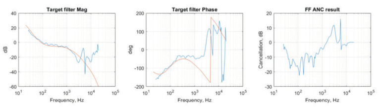
It is also important to note that FF ANC may not only reduce the sound in the ear but also increase it. Too high of ANC filter gain at higher frequencies leads to the so-called waterbed effect, and the final FF ANC effect is above 0dB. This is not desired, and the solution is to reduce the ANC filter gain at those frequencies. However, this will also make cancellation worse at the frequencies where it is effective. ANC designers must take this trade-off into account. Luckily, passive attenuation is suitable in high frequencies and helps to mitigate the waterbed effect.
The previous paragraphs explained the FF ANC mechanism and the sources of its limitations. Now it is possible to analyze the effect of microphone characteristics on FF ANC.
An FF microphone is a part of the active transfer function. The shape of its magnitude and phase response adds to other components, like the speaker. The simulation in Figure 5 shows a comparison of two FF ANC systems. The baseline solution has 30Hz LFRO microphone and 24µs microphone ASIC digital latency. The modified microphone has 10Hz LFRO and 3µs latency and assumes 30µs lower ANC processing latency. One can observe the change in the shape of the active transfer function on the chart below. The target filter curve changes and the fitted FF filter transfer function is updated accordingly.
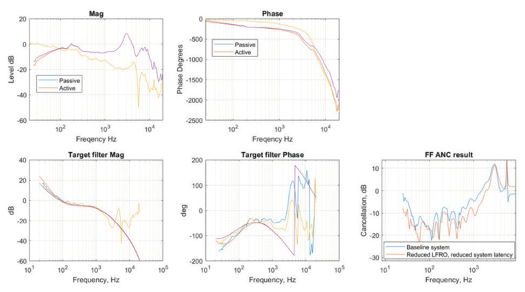
As expected, the microphone’s broader and flatter magnitude and phase response flattens the active transfer function, making target filter curves flatter and easier to fit with DSP filters in a wider frequency range. A better fit of ANC filters leads to better ANC cancellation in a wider frequency range and pushes the waterbed region to higher frequencies. Specifically, lower microphone LFRO improves the low-frequency limit of FF ANC, while lower system latency improves the high-frequency limit of FF ANC.
Should it be concluded that FF mic LFRO for TWS ANC headsets should be as low as possible? It will improve ANC, but other system trade-offs are essential to consider (e.g., wind noise mitigation). If the microphone LFRO is too low, the system will be too sensitive to wind noise, which is rich in low frequencies. High-frequency FF cancellation improves with lower system latency. The total latency value includes microphone and DSP processing. All components of the system need to be improved for the best results.
Feedback ANC
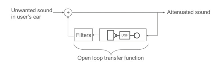
A concept diagram for the FB ANC system is shown in Figure 6. Unlike FF ANC, the entire system functions inside the user’s ear. Input signal into the FB loop is the residual noise after passive and FF cancellation. The FB microphone captures sound, and the DSP path applies FB ANC filters. Then, the resulting signal is played through the speaker. The open loop transfer function includes all system components, assuming no coupling from the output back to the input. Usually, it is measured in the analog domain by feeding a constant signal to the speaker and measuring the output of the DAC of the ANC chip.
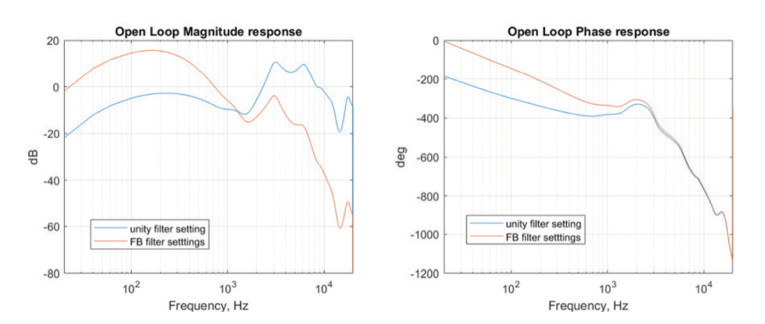
To maximize noise cancellation in an FB system, the open loop transfer function must apply as much gain as possible while maintaining the system’s stability. There are mathematical techniques to describe this trade-off. For example, phase and gain margin analysis can be used. Figure 7 shows a FB ANC system’s open loop transfer function. With filters set to unity, one can observe the starting point of algorithm tuning. Next, the filters are picked to maximize FB cancellation while the waterbed effect and stability are still acceptable. In this example, filters are constructed from 20dB gain, 180° phase inversion, and second-order bandpass filter from 1Hz to 425Hz.
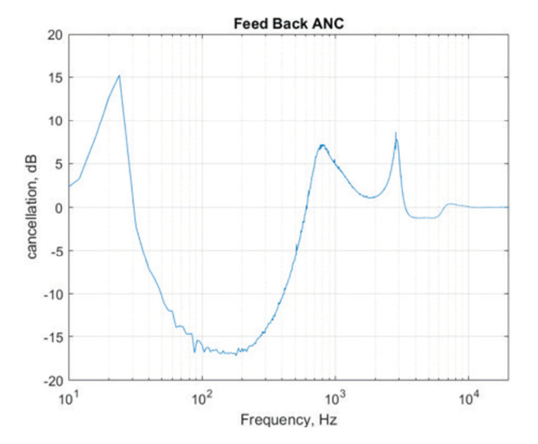
The result of the tuned open loop transfer function is given in Figure 8 as the FB ANC curve. Maximum achievable attenuation is more than -15dB at around 200Hz. The open loop transfer function at that frequency has maximum gain and phase inversion close to 180° in the low-frequency range, and at 1kHz to 3kHz, the FB system amplifies the signal. This is an unwanted waterbed effect. Phase and gain margins are reduced at those frequencies, but the system is still stable. The above 5kHz open loop transfer function is sufficiently attenuated, and the FB loop does not impact the signal.
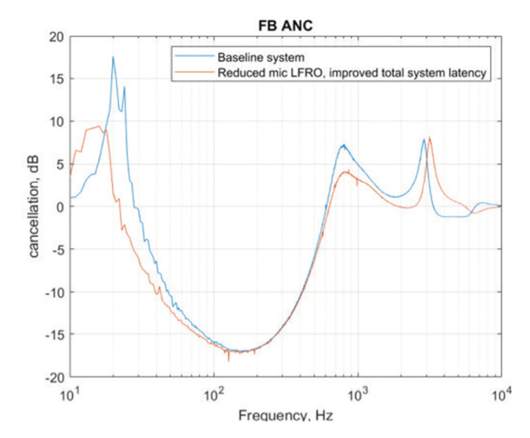
The next step is to evaluate the impact of microphone specification on the operation of the FB ANC loop. As in the FF process, the microphone transfer function is one of the components of the open loop transfer function. The lower microphone LFRO makes it flatter at low frequencies and thus improves the gain margin. Lower system latency leads to less steep phase response and improves phase margins in the high-frequency range. Figure 9 shows the impact of LFRO and latency improvement on FB ANC. Effective bandwidth is enhanced on both sides, reducing the waterbed effect.
In summary, the microphone requirements for the best FB ANC have the flattest possible magnitude and phase frequency response. Lower LFRO improves FB ANC in the low-frequency range, and lower microphone latency improves FB ANC in the high-frequency range. It is important to note that lowering the microphone LFRO too much can have negative consequences. Head or jaw motion and other forms of human physical activity can lead to high SPL, low-frequency signals generated inside the ear canal while wearing a TWS headset. Having LFRO sufficiently high protects the system from unwanted overload.
Transparency Mode
Earlier we stated that a TWS headset provides passive attenuation in the ear. Simply put, it acts like an ear plug attenuating high-frequency signals. Hearing the outside world without such passive attenuation is important in some use cases. This is achieved in what is called transparency mode. The block diagram for this (Figure 10) is similar to that of the FF system. The difference is the target signal inside the ear. Unlike FF ANC, where the goal was to cancel out the sound that couples into the ear, the purpose of transparency is to match the transfer function of the open ear.
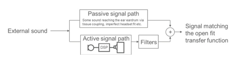
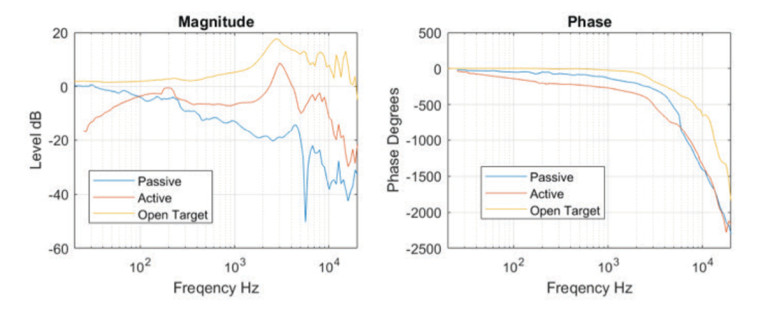
Figure 11 shows the target open fit transfer function and active and passive signal path transfer function discussed in the FF section. As expected, the curve is generally flat with high-frequency resonances in the ear. The active signal path multiplied by the transparency mode filters combined with the passive signal path must match the open target curve. At this point, it is already clear that transparency mode will require lots of gain applied to the microphone signal.
Target transparency mode filter coefficients can be derived by solving a simple equation described as:
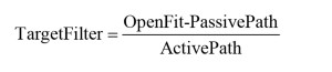
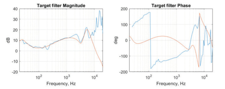
Like FF ANC, target curves are fitted with available filters in the DSP chip. An example is given in Figure 12. Note that the filter magnitude is above 0dB, and lots of gain is applied to the microphone. Matching perceived loudness will be the most noticeable effect in transparency mode. Of course, the shape of the phase response curve can be audible due to temporal distortions. Given the flexibility of DSP filters available, the match of magnitude filter curve is considered more important in this case for the audible experience of the user in transparency mode.
As a result of this algorithm, the user of the TWS headset will hear sounds that closely resemble the experience with an open ear. However, it is critical to recognize that the microphone itself is a noise source. Microphone noise will be amplified by the DSP coefficients and played through the speaker. This means the noise floor in the ear will increase. If the environment around the user is a sufficiently loud microphone, the noise will be negligible, and the system will operate as intended. However, the microphone will dominate the in-ear noise floor in a quiet environment. Sometimes this effect is described as transparency mode hiss.
Figure 13 compares the microphone input-referred third-octave noise spectrum and the same characteristic of the transparency mode system. The Integrated A-weighted noise difference is 13dB. In this example, the user might start hearing the transparency mode hiss if the environment is below 39dB SPL.
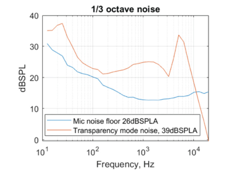
The level of transparency mode hiss drives the requirement to use microphones with as high as possible SNR. Higher SNR and, thus, lower microphone noise expands the range of use cases for transparency mode where the user will not experience the hiss.
Conclusion
We described the operation of FF ANC, FB ANC, and Transparency mode, along with the critical microphone specifications that lead to improved user experience. This exercise shows that microphone latency needs to be reduced as much as possible, and that a proper algorithm tuning allows better FF and FB ANC in the high-frequency range. It also reduces unwanted high-frequency amplification, known as the waterbed effect.
We have also seen how microphone LFRO needs to be set optimally. With proper algorithm tuning, lower LFRO allows for better cancellation in low frequencies for both FF and FB ANC. However, LFRO cannot be set too low to avoid wind noise issues with the FF microphone and infrasonic overload issues with the FB microphone.
Finally, we have shown that microphone SNR must be as high as possible to reduce audible hiss and expand use cases for transparency mode.
Knowles has invested significant time in understanding how microphone selection influences the final user experience. From these findings, Knowles has developed a comprehensive portfolio of MEMS microphone models that can help manufacturers achieve the best noise cancellation possible. With these specifications in mind, these MEMS microphone models can ensure optimal performance in TWS ANC applications. aX
Resources
Knowles V2S Demo, https://vimeo.com/811043420
 About the Author
Nikolay Skovorodnikov is a Senior Manager Applications Engineering, MEMS Microphones at Knowles, based in Itasca, IL. Previously, Nikolay was a Graduate Researcher at University of California, Davis, Department of Chemical Engineering and Materials Science, and held research positions at Nano-Optic Devices. Nikolay received a Bachelor of Science degree from Lomonosov Moscow State University (MSU).
This article was originally published in audioXpress, November 2023