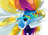
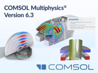
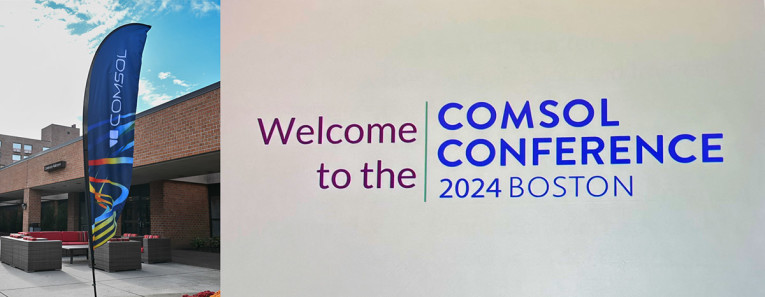
After a five-year gap for in-person conferences from COMSOL, the 2024 event in Boston, MA - part of a planned series now expanding to Europe (Florence, Italy) and Asia (Shanghai, China) - was a very successful return. audioXpress was invited to attend, as more and more audio developers and manufacturers use COMSOL's Acoustics Module, Structural Mechanics Module, and the AC/DC Module, among others integrated in the leading Multiphysics modeling and simulation software.
More than 200 attendees enjoyed the three-day event, attracting simulation specialists and researchers looking to rejoin the growing community. Every COMSOL Multiphysics module, interface, and use-case was there for the experiencing in mini courses, talks, posters, exhibitors, and bespoke demos in the Learning Center. The new features of COMSOL 6.3 were on display and in discussion.
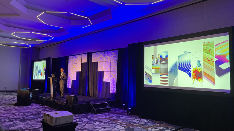
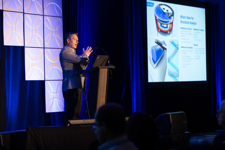
In his keynote for the event, Bjorn Sjodin, COMSOL’s Senior Vice President of Product Management, proudly exclaimed, Simulation in Acoustics was "up front!"
The Acoustics Module was indeed up front and center on Day 1. It is the first, and, so far, only module to add the explicit time domain solution with the aid of a graphics processing unit (GPU), if there is a NVIDIA card present. Complex, GPU-enabled calculations are now up to 25 times faster. The extreme example shown by COMSOL at this Boston event was a model with 49 million Degrees of Freedom (DOF) that was solved in 1.5 hours! The significance for anyone that has been using the COMSOL Acoustics Module will take your breath away. In addition, Sjodin proclaimed the addition of Poroacoustics in the time domain, Thermoviscous Acoustics with SLNS (Sequential Linearized Navier-Stokes), and Electromechanics Couplings for Shell and Membrane elements.
Acoustics and Loudspeakers
The COMSOL Multiphysics software can be paired with its Acoustics Module add-on product to model a large variety of acoustic phenomena using specialized acoustic models and solvers. Multiphysics phenomena, such as acoustic–structure interaction, piezoelectricity, or convected acoustics, can be included.The software's modeling capabilities range from microacoustics with thermoviscous effects to concert hall simulations using ray tracing. Specifically, the Acoustics Module has a functionality that enables users to combine model results across physics and numerical methods for multiscale simulations. The module also comes with an extensive variety of boundary conditions for frequency - as well as time-domain simulations.
The most popular models that users run in the COMSOL Acoustics Module are for transducers and Smart Devices: smart speakers, soundbars, microphones, MEMS, sonar, mobile phones, and smart TVs.
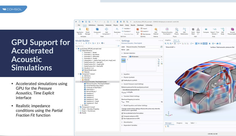
Automotive applications are also very popular not only for cabin acoustics and noise transfer paths, loudspeaker integration and performance in the vehicle, but for ultrasound sensors. An automotive example demonstrated a sub modeling of a component and applying the sub model results to a larger model. This is how large-scale models can be tackled: taking good specific results and applying them to the larger model instead of generalized omni-directional point sources, which would be a less accurate approach.
Multiphysics always included multiple numerical methods, but those continue to expand with finite element method (FEM), boundary element method (BEM), Ray Tracing, Discontinuous Galerkin-Time Explicit (the most memory efficient wave-based method), Hybrid Methods (coupled FEM-BEM, FEM to Ray, lumped elements, and electroacoustic elements).
The most interesting update in version 6.3 was the addition of GPU support for Accelerated Acoustic Simulations, as mentioned. It’s currently only available for non-matrix-based time domain models and works with NVIDIA chips only. NVIDIA's RTX-A6000 Ada was used for the modeling examples. One of the prime examples had an automotive cabin acoustic model with 49 million DOFs, which was solved in 1.5hrs using the GPU compared to the 19 hours solution time, when solved on two cluster nodes (i.e., two processes per node, using an Intel Xeon w5-2455X CPU with 12 cores). For the best wave-based room model with 30 million DOFs, COMSOL reports a 25-times speed up in solution time.
Jinlan Huang, Principal Applications Engineer for Acoustics at COMSOL anticipates an immediate impact of GPU support will be felt by smart speaker and smartphone developers using COMSOL to simulate the effect of room acoustics and car cabin acoustics on voice interaction and audio playback. Also, with room acoustics and car cabin simulations running transient analysis for impulse response results.
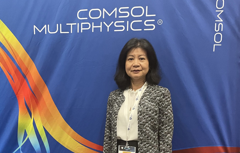
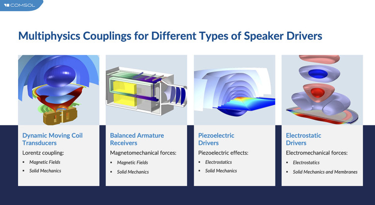
Jinlan was also very excited about the improvements to Electromechanics coupling to a membrane or shell element. Before it was necessary to set up the coupling manually, because the coupling was only available to a solid element. Now, with version 6.3, a new Electromechanics, Boundary multiphysics coupling has been added for coupling Electrostatics to the Membrane or the Shell physics interfaces. This simplifies setting up models of microphones and electrostatic speaker drivers.
In addition to that, she felt that a very powerful improvement came with thermoviscous solutions becoming faster in the Acoustics module by making available a new formulation using Sequential Linearized Navier-Stokes (SLNS). It is faster for linear solutions than Full Linearized Navier-Stokes (FLNS). It is in the frequency domain only, but very useful for large system simulations to include the thermoviscous boundary layer losses.
Before version 6.3, Thermoviscous Acoustics in a complex geometry was always Full LNS. This is hard to use in a full device. The model became too big. If Full LNS wasn’t feasible, then using Narrow Region Acoustics (applicable only in waveguides of constant cross section) or using Thermoviscous Boundary Layer Impedance (applicable only in cases where boundary layers are not overlapping) was necessary.
The SLNS method fits in between these and the FLNS, completing the tool set. SLNS is very similar to FLNS and requires only slightly more computation power than Narrow Region Acoustics (RLF) and Boundary Layer Impedance methods. For SLNS, the wavelength needs to be larger than the thickness of the boundary layer, which is the case for small devices. In devices where most of the damping happens at sudden geometry changes, like a sudden expansion, SLNS will be less accurate than FLNS. The method includes all the rotational flow components in the boundary layers but not those existing in regions with redirectional flow due to a sudden expansion. For detailed modeling of, for example, perforates or microperforated plates use the FLNS.
Another improvement is to be able to use Poroacoustics in the Time Domain, where poroacoustics-equivalent fluid is used. Poroacoustics domain materials will have frequency-dependent properties available. Also new is Analytical Port Modes for Linearized Potential Flow, which includes standardized modes, simplified modal transmission, and source expansion. And, an acoustic treatment boundary Calculator App has been added.
In a FEA model the app uses random angle of incidence for layered porous materials to determine the boundary treatment. It can be used in a sub model for application to a Ray Tracing model.
And, finally, a method has been developed for using the Partial Fraction Fit function to model realistic frequency dependent impedance conditions, or material with a bulk damping that is frequency dependent. This is not a feature yet, but the method has been developed. It uses frequency dependent data in the time domain. It can also be applied to nonlinear and transient absorption coefficients, and can determine the heat source accurately for medical, tissue-based models, but also any nonlinear material that might be found in audio.
It also makes it possible to more accurately calculate energy dissipation for wave propagation with higher harmonics. The method can calculate a subcomponent’s nonlinear equivalent circuit. It uses the Partial Fraction Fit function, determines the real residue (amplitudes) and pole (damping) response from the data, and creates an equivalent circuit model. A large nonlinear (e.g., THD) model becomes feasible with a lumped circuit model as a sub model. The methodology came out of the need for a complex data set for use in nonlinear analysis, which needs the complex damping. Earlier work on THD used an existing equation for a Volterra series expansion. With this method, the actual equation is derived from the data set.
What’s New for Geometry Import and Meshing
The meshing step in the modeling and simulation process directly influences the accuracy, computation time, memory requirements, and solution interpretation of a simulation. COMSOL Multiphysics offers fully automated meshing that accounts for both geometric information, such as surface curvature, and settings for the modeled physics phenomenon. For example, the software can automatically adapt the mesh size to resolve wave propagation problems or use boundary layer meshing for walls in CFD.
The automatic meshing functionality is complemented with powerful yet user-friendly meshing functionality for manipulating a mesh generation sequence to create a mesh of the user’s choice. For instance, the user can create a hexahedral mesh for one subdomain and tetrahedral or prismatic meshes for other subdomains. Partitioning the geometry into subdomains allows for the automatic mesh engine to use more compatible elements for different subdomains. Creating a mesh from results plots is most useful for verifying topology.
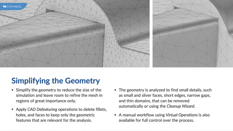
New for version 6.3, for simplifying the geometry is a CAD defeaturing operation, where the geometry is analyzed to find small details automatically, or a Cleanup Wizard can be used. Also new for meshing touching objects, there is the automatic creation of a conforming mesh, keeping separate different volume regions. There is an option to mesh parts individually with matching or non-matching meshes on the touching surfaces. Finally, the defeaturing operation is automatically adapted to resolve geometric features, and it can be controlled by predefined element settings: size, size expression, or distribution.
And although the new features for detailed Size parameters have just emerged from Beta testing, they should prove to be a time-saver and improve the modeling workflow.
Simulation Applications Development
The Application Builder, included in the COMSOL Multiphysics software, has enabled a larger community of scientists, researchers, and engineers to benefit from multiphysics modeling and simulation. Modeling experts can use the Application Builder to create simulation apps, which are easy-to-use interfaces that are made from existing COMSOL Multiphysics models, allowing users to control the settings of the simulation directly in the app. The app user is then focused on the input parameters and computational results that matter, without requiring foreknowledge of the underlying model. They can run on a browser on a web-based server.
The Application Builder is extended by the COMSOL Compiler, which compiles simulation apps into standalone executable files. These files can then be distributed to anyone and run anywhere. This is a simple and customized user interface for internal organizational use or end user customer use (who wouldn’t have a COMSOL license). Stand-alone or web-based applications for running model parameters remotely or without COMSOL resident on a PC or laptop can also be created.
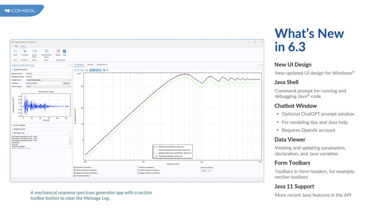
New features in 6.3 include Java Shell for running debugging code, Chat or window (Optional ChatGPT prompt window, modeling tips and Java help, uses your existing OpenAI account), Data Viewer (viewing and updating parameters declaration and Java variables), and Java 11 Support (more recent Java features in the API). The user can also export data or graphics, either in reports or to whatever variable the user specifies in Java. Simple parameter changes or geometry changes (which requires a new mesh build) can be attributed to a button or done automatically in the application. Expertise in Java is not required.
Jinlan also felt that the Application Builder, Java Shell, and Chatbot will lower the barrier to users who want to try modeling by allowing them to ask for the model to be built for them, based on what they need.
Sonos Keynote
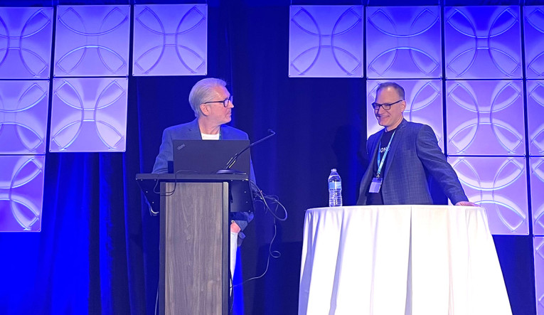
A highlight of this COMSOL conference in Boston was a keynote by Doug Button and Joe Jankovsky from Sonos. The title was "Acoustic Simulation for Immersive Audio."
In their own words, Sonos is driven to make audio products that put the listener first, and finite element simulation has continued to be an important part of this mission. In previous presentations at COMSOL events, Sonos team members have shared how they use the Acoustics Module in COMSOL Multiphysics. In this keynote, the two focused on several examples of how Sonos uses the finite element method (FEM) to analyze and improve the acoustic directivity of its products. Sonos has leveraged COMSOL acoustic simulation to create immersive listening experiences in its connected systems. They discussed the acoustic simulation process of the Sonos Era 100 and Era 300 smart speaker design, using COMSOL Multiphysics as their core modeling analysis tool to develop audio transducers and loudspeaker systems and optimize microphone placement for voice control.
"Analysis is used for optimization," said Joe Jankovsky a Lead Simulations Engineer at Sonos, "but can also be used to create something new." Doug Button, Distinguished Audio System Engineer for Sonos, with a rich history of quality design work dating back to his days at JBL Professional, followed up Joe’s introduction. "Innovation is iteration," Doug said. "If I can draw it, I can measure it, and model it."
The Sonos journey to realizing an immersive speaker started with slot loading experiments for getting wider dispersion using COMSOL to perform those experiments. The first version of the Era, the Era 100, had a range of 200 degrees of dispersion in both the tweeter and the woofer. For the tweeter and woofers, beam quality was investigated, comparing small horns versus direct radiators. The results from the modeling proved that horns, or a waveguide, provide us with better directivity.
Then they detailed the design of an all-in-one, stereo speaker with wide dispersion, which became the Era 300. COMSOL was used to optimize the separation of the side lobes for each speaker and horn, so the perceived mage is distinct.
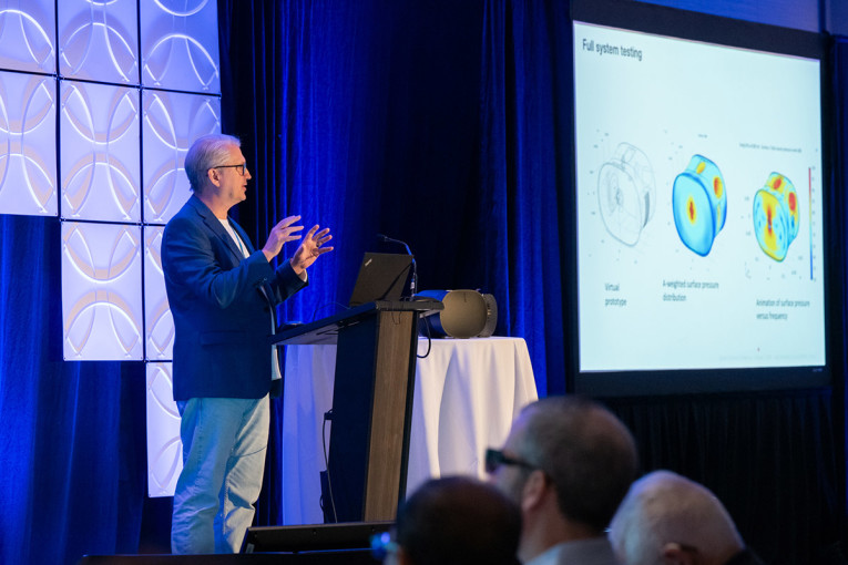
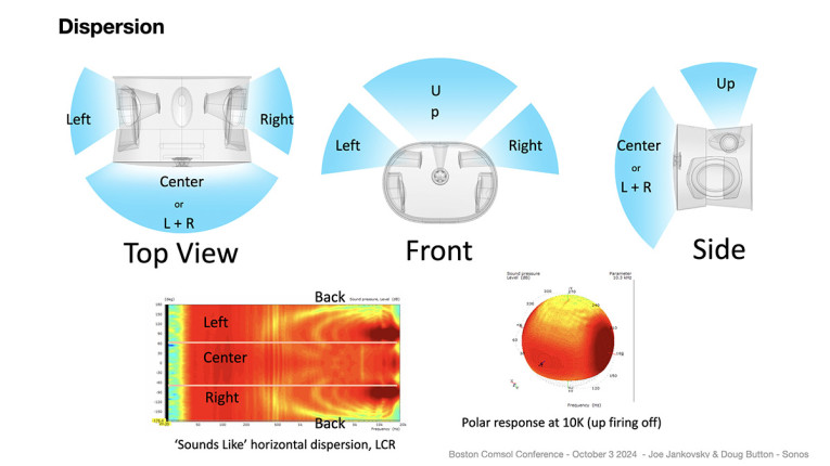
Deciding on the shape and working on diffraction came next. This is usually the battle between the best, ideal engineering design and the industrial designer’s needs and wants. The iterations between engineering design and industrial design playout in simulations, all validated with measurements of a partial or full prototype.
Doug then tested his ideas for the high-frequency transducers and the aperture and the phase plug for the compression driver in COMSOL, optimizing the space around the driver’s surround and the plug. Tightening of the space around the surround created an air suspension that could reduce phase cancellations and smooth out the response. The woofers and their surrounding substrate were modeled on their own and then put together with the high-frequency horns in COMSOL to find the best place for the microphones on the box surfaces, so they would not experience interference from the playback.
"Iteration is very fast with COMSOL. It’s a great creativity booster. And takes virtual prototyping to a new level," said Doug who admitted to typically doing more than 1000 COMSOL iterations to every physical prototype.
xMEMS Research
Another guest speaker in this COMSOL Conference was Michael Ricci, Sr. Director of Engineering at xMEMS, who presented his simulations of the ear canal pressure used to illustrate the valve control available in their DynamicVent solution, a specific MEMS design with a valve that opens or closes by sensor fusion input from the earbud DSP and enables the benefits of both an open-fit (spatially aware) and closed-fit (occluded) earbud design. This allowed xMEMS to control the ear canal pressure to avoid elevated in-ear monitor gain that comes from a closed ear canal without external acoustic awareness.
Michael also had on display many of the in-ear XMEMS monitor examples. The listening experience showed the value of a transducer with only 2 DOF. The lack of motor structure removes the inherent delay in traditional transducer design. The lack of latency in the transduction is significant. The group delay is in the microseconds: 15ms. This becomes most important for the immediacy needed for superior spatial rendition. Michael also shared some of the data to support that research, which he also has recently introduced in his CanJam talk "It’s About Time."
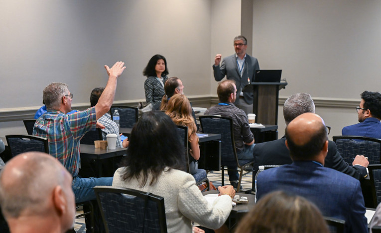

At the end of three days, it was clear to see why audio developers find COMSOL to be increasingly their tool of choice for research and simulation. The intuitive interfaces, which keep improving more and more with each release, and the ease of multiphysics coupling and sub modeling are prime reasons for this. Behind that is a depth of understanding in the details and complexity of the physics that small devices, complex assemblies, and large models require.
The ability to work face-to-face with those who have that expertise and to share the user’s own practical experience with COMSOL researchers and other users is the value of these in-person conferences. COMSOL is committed to keeping them going in all the regions of the world that they cover. And they will continue to be a popular choice for innovation leaders to attend.
The next opportunities, with different speakers and presentations, will be in Florence, Italy (October 22–24) and Shanghai, China (October 31–November 01). aX
This article was originally published in The Audio Voice newsletter, (#488), October 10, 2024.


