Being of the persuasion that insists on tubes for highest quality sound, I believed that a vacuum tube implementation of the Borbely RIAA architecture might make a superb-sounding phono stage. Thus, when I needed a new preamp for critical evaluation of other components in early 2001, I began work on the design in this article.
Background
For those unfamiliar with the playback requirements of phonograph records — specifically the long-playing microgroove record (LP) — perhaps a brief overview is in order. The process of cutting discs is not a trivial one. The modern feedback-coil cutting head operates as a “constant-velocity” device, in which the recorded signal produces a groove modulation with constant velocity with respect to frequency. This is in contrast to the “constant-amplitude” system, where the groove modulations exhibit constant amplitude with respect to frequency. In the constant-velocity system, groove amplitude is in inverse proportion to frequency when driven with a constant voltage.
The net result of this is a 6dB-per-octave rise in groove amplitude towards low frequencies. To ensure that record cutover (where groove amplitude is so large that the cutting stylus blasts through the groove wall) does not occur, the RIAA specifies that all discs cut in the US be equalized with a first-order attenuation of low frequencies below 500Hz, flattening at 50Hz. To improve signal-to-noise ratio, a high-frequency pre-emphasis is added with an initial time constant of 75μs (approximately 2.12kHz). The RIAA playback equalization curve is, therefore, the inverse of this characteristic, with a low-frequency boost starting at 500Hz and leveling off at 50Hz, and a high-frequency cut starting at 75μs.
Allen Wright has pointed out that there is obviously a limit as to how high in frequency the recording boost can prevail,3 and this is generally accepted to be in the neighborhood of 50kHz. Therefore, in most modern phonograph preamplifiers, the high-frequency deemphasis levels off above this point. It would seem that a first-order differentiator spanning the range of 20Hz to
20kHz during cutting would be much easier to implement and decode, and might sound better. Perhaps some more studied readers could enlighten me about why the RIAA decided on two first-order transfer functions separated by only a couple of octaves.
Implementing the RIAA equalization characteristic in a low-noise disc playback amplifier has always been a formidable task, and the two principal approaches have been hotly debated. Borbely’s solution is to use a wideband voltage amplifier direct-coupled to a passive low-pass filter for the 75μs rolloff, and then an amplifier with active shelving EQ for the 500Hz boost. Erno Borbely deserves kudos for his extremely original and effective solution. Please refer to his original article1 for a detailed account of his design considerations.

The Design
My phono preamp (Fig. 1) begins with a common cathode triode amplifier used as a linear voltage gain stage. I chose the 5842 for its outrageously high transconductance (gm) of 25mA/V at the published nominal operating current (25mA). High transconductance is absolutely necessary for low noise, and is important when the signal source is good for only 3–4mVRMS at 1kHz (typical output for a moving-magnet phonograph cartridge).
Quiescent plate voltage is set to approximately 100V with a plate current of 10mA. This lower current results in slightly lower gm (20mA/V), but it is still much better than the typical low-gm, high-μ twin-triodes such as the (miserable) 12AX7. Amplification factor (μ) at this operating point is 42, and dynamic plate resistance (rp) is 2kΩ. Plate load resistor (RL) is 22kΩ, selected to be more than ten times the plate resistance for excellent linearity and high gain. B+ is 320V, regulated.
I used a 100Ω cathode resistor to bias the tube to the required grid-to-cathode potential of −1V, and inserted a 2200μF bypass capacitor to maintain low effective plate resistance and encourage maximum gain. Input grid-leak resistor can be 47kΩ or whatever the cartridge manufacturer specifies for proper loading; the same applies to any capacitance added to the input. Just remember that amplifier input capacitance due to the Miller effect is already around 75pF, and be sure to include cable/tonearm capacitance, which is effectively in parallel with the input, when computing the necessary remainder.
For the definitive analysis on proper cartridge termination, refer to Raymond A. Futrell’s excellent article (see References). This stage is direct-coupled to a shelved low-pass filter consisting of a series 22kΩ resistor and shunt RC network. Admittedly, a larger series resistor would have presented a lighter load for the first stage at high frequencies, but only at the expense of midband gain, and an effective high-frequency load of five times the plate resistance is still quite good. The RC network consists of a 3.3nF capacitor and 1kΩ resistor.
Assuming second-stage input loading of 220kΩ and bearing in mind that the effective series resistance includes the output resistance of the stage (rp || RL), the turnover point is within 1% of 75μs with a shelf within about 3% of 50kHz. Midband gain is approximately 34.7, or 31dB, again assuming the aforementioned loading conditions, and including midband loss due to the 75μs filter.
Fans of the legendary Charles Boegli will immediately recognize the second amplifier stage, which is configured as an anode follower , or inverting voltage amplifier with shunt-derived/shunt-applied feedback. I chose shunt/shunt feedback for its profoundly better subjective sound quality over conventional series-applied feedback. Input series resistor is 220kΩ in accordance with previous assumptions, and this is in series with a decoupling capacitor to block the standing plate voltage from the first stage. The feedback resistor is also 220kΩ for approximately unity midband gain, and the boost below 500Hz is courtesy of a series 1.45nF capacitor, which can be selected from 1.5nF capacitors.
For the 50Hz shelving frequency, I encountered problems with insufficient open-loop gain; neither a shelving resistor across the feedback RC network nor tuning the input network to 50Hz gave adequate results because of this. After much agony and frustration (and a stern refusal to add more gain stages), I discovered empirically that a bit of “English” applied to the decoupling capacitor gives remarkably accurate conformation to the RIAA curve. The final value of 18nF gives a predicted shelf below 36Hz, but the actual turnover is very nearly 50Hz. Grid-leak resistor is 2.2MΩ, selected to be ten times the input and feedback resistances to minimize the possibility of interaction. Output capacitor is 2.2μF, and the entire phono stage will drive loads down to about 50kΩ without affecting gain or RIAA accuracy.
Construction
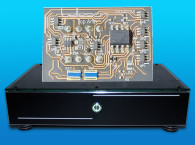
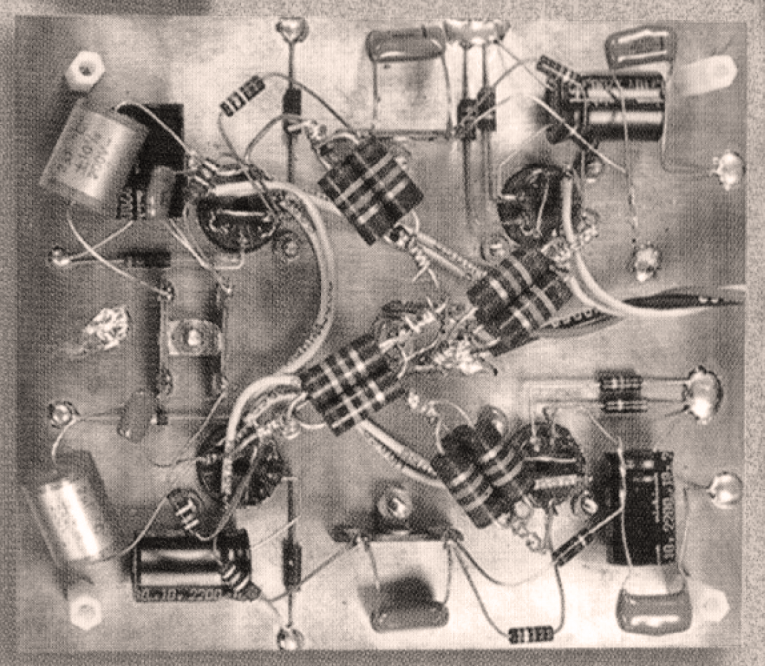
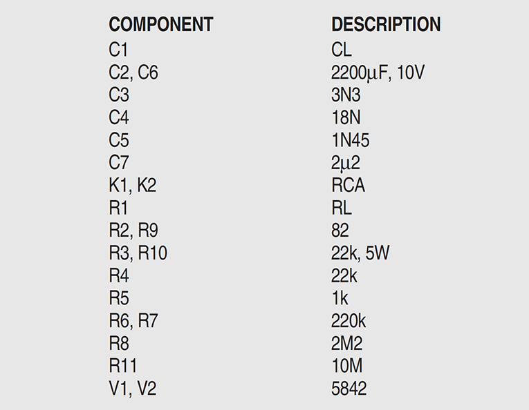
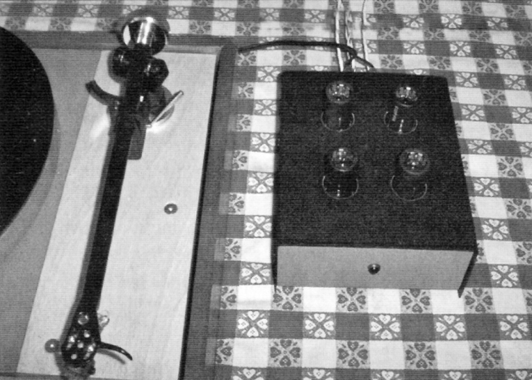
I built the prototype on a piece of copper-clad epoxy PC board material (Photos 1 and 2). The copper makes a very good ground plane, which is important for a low-hum preamplifier. The circuit is point-to-point wired using terminal strips, which I believe has far superior sound to PC wiring. Resistors are Allen-Bradley carbon composition with 5% tolerance, which I prefer over film types for their sound despite less-than stellar noise performance (although if de-rated to approximately one-third their nominal power rating, noise and stability are dramatically improved).
Each plate load resistor is composed of three 68kΩ, 2W resistors in parallel to make a composite resistor within 3% of the specified value. The remaining resistors are all 1/2W types. Decoupling and equalization capacitors are metallized polypropylene Sprague “Orange Drops,” which I use here because they are cheap, available in surplus, and pretty good in sound quality. The 2200μF cathode-bypass capacitors are Nichicon electrolytics. IERC heatsinks are used, which also serve to shield the tubes.
Testing
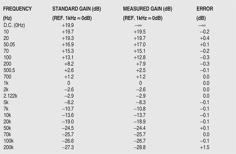
I tested the preamplifier for frequency response and equalization accuracy using a Fluke 407DR laboratory power supply, Hewlett-Packard 33120A 15MHz signal generator, and Tektronix AA501 distortion analyzer used as a high-precision AC voltmeter (Table 1). Standard values are taken from a modified version of a computer program found in Morgan Jones’ excellent volume, Valve Amplifiers.
As you can see, the equalization is accurate within 0.4dB from 10Hz to 100kHz. Most of the variation occurs between 50 and 500Hz, probably because I made no concentrated effort to select parts. The 1.45nF capacitor previously mentioned is most likely the culprit, being directly responsible for the 500Hz turnover frequency. Gain at 1kHz is 30.8dB, resulting in only 140mV output from a 4mV cartridge, so a line stage will be required to drive most power amplifiers. This situation is similar to that encountered with tube-type FM tuners.
I then tested the preamplifier for sonic quality using a Lambda Model C-481M-505 regulated power supply, Thorens TD-125 turntable, Premier MMT tonearm, and Shure M97xE moving-magnet cartridge through home-brew tube power amps and speakers and a variety of (mostly jazz) LPs. While this is a simple setup by audiophile standards, the sonics can hardly be described as modest. The sound of this preamplifier is clean, natural, and balanced, without a trace of harshness or exaggerated “tube warmth.” Detail is excellent without being obnoxiously analytical.
The Sheffield Labs direct-to-disc recording of Harry James, the King James Version, yields so much realism that the Chair of the EE department at Wright State University commented, “I’ve never heard recorded music sound like this before.” Hum and noise are truly negligible. In fact, this preamp has been a fixture in my main hi-fi system for over two years, shattering the normal lifespan of a component by at least 18 months.
If and when time permits, I plan to construct a second stereo preamplifier using non-inductive wirewound precision resistors and oil-type Sprague Vitamin-Q capacitors. I strongly encourage any reader looking for a high-quality phonograph preamplifier to try this one. For those not willing to use NOS 5842’s, a kit version of this preamp using a paralleled 6922 in place of each is available from Tritschler Precision Audio (see author's website below). aX
Acknowledgments
Special thanks to the EE department at WSU for their encouragement and use of their test equipment.
References
1. Borbely, Erno, “The Borbely Preamplifier,” The Audio Amateur, 4/1985, pp. 7–21.
2. Marsh, Richard N., “A Passively Equalized Phono Preamp,” The Audio Amateur, 3/80, pp. 18–27, 58–59.
3. Hagerman, Jim, “On Reference RIAA Networks,” Audio Electronics, 2/99, pp. 10–13.
4. Futrell, Raymond A., “The LP Terminator,” aX Jan.’03, pp. 8–15.
5. Boegli, Charles, “The Anode Follower,” Audio, December 1960, pp. 19–22.
6. Jones, Morgan, Valve Amplifiers, 2nd ed., London, Newnes, 2000.
7. National Semiconductor Corporation, Audio/Radio Handbook, Santa Clara, National Semiconductor Corp., 1980.
8. Author's Website: https://joetritschler.com/index.html
Borbely RIAA with Tubes Revisited
In the October 2003 aX, I described a stereo phono preamplifier using 5842 triodes and an equalization scheme that was inspired by an 1985 article written by Erno Borbely for The Audio Amateur. Several readers built 5842 preamplifiers, including a gentleman in the United Kingdom who called it a “living, breathing instrument,” for which I’m very grateful. Since that original article, I’ve made many changes to the unit and present them here. The preamplifier remains the centerpiece of my system and I use it constantly, often playing several records per day.

The Circuit
Borbely’s approach to a phono preamp in 1985 can be described as half-active and half-passive; a linear gain stage up front is followed by a passive low-pass filter for the RIAA 75µs rolloff and an active shelving equalizer for the 500Hz/50Hz low-frequency boost. My preamplifier replaced Borbely’s discrete transistor circuitry with two very high-transconductance framegrid tubes, and the result was very good subjective and measured performance. I’ve elected to keep the basic topology of this circuit intact through all the changes. A common-cathode amplifier stage provides voltage gain at the input, followed by an RC low-pass filter; then a second amplifier stage with anode-follower negative feedback implements the RIAA bass boost courtesy of a series capacitor in the feedback impedance. With only two active devices, it’s indeed a very simple circuit.
Design revisions encompass the following: a new biasing scheme and operating point, a redesigned low-frequency section that offers higher overall gain, a modification to the extreme high-frequency response of the preamplifier, and special attention paid to equalization accuracy and component technology. The result is a preamplifier that is a major improvement over the original in both objective and subjective terms.
Biased Opinion
Rather than a traditional cathode bias resistor with bypass capacitor, each stage of the updated preamplifier (Fig. 1) uses a Lumex SSL-LX5093ID LED to set its cathode voltage, a technique inspired by Morgan Jones in the third edition of his book Valve Amplifiers. The first time I saw LED bias—circa 1999 — in the first stage of a power amplifier, my reaction was to make fun
of it. Using a nonlinear device in the very circuit position from which the input signal is derived seemed ridiculous at the time. Mr. Jones made a very convincing argument, however, so I tried it and listened to the difference. It turned out to be a very significant sonic improvement.
LED bias has pros and cons. LEDs tend to drop a constant voltage over a fairly wide range of operating current. This means that their dynamic resistance is very low. I extrapolated 13Ω from the manufacturer’s datasheet at the chosen operating point of 15mA and used it in my computations. The significant advantage of this is that a cathode bypass capacitor is no longer needed. The downside is that the constant-voltage behavior more or less constitutes fixed bias, losing the cathode resistor’s inherent advantage of providing DC feedback to stabilize the tube’s operating point. This is of particular concern with high-transconductance tubes since, by definition, small changes in bias produce large variations in plate current.
As it turned out, I did need to plug in a few different combinations of 5842s to find pairs that biased similarly channel-to-channel, but the improvement in sound was most worthwhile. Incidentally, there’s nothing special about these particular Lumex LEDs; they were simply available locally in surplus. Morgan refers to “cheap red LEDs” in his book, but I tested a few different types and they do differ slightly in voltage (and presumably resistance), and seem to be very consistent within a given part number.
My theory is that a cathode bypass capacitor is likely to be much more audible than any power supply bypass capacitor. The reason is that even though the dynamic plate current of a single-ended amplifier stage flows through both of them, any AC voltage developed by the power supply capacitor across its impedance (including nonlinearities and parasitic components) will be attenuated by the amplifier’s power supply rejection (which is high in this circuit). Whereas, any nonlinear AC signals appearing across the cathode bypass capacitor are placed right into the input grid-to-cathode signal and amplified. This effect seems most pronounced in high-transconductance stages.
Switching to LED bias in this preamplifier brought out reverb tails and other nuances that had previously been missing, probably due to electrolytic capacitor imperfections. Of all the component changes made, this was the most audible, resulting in a major improvement in detail and a clearer, less-fatiguing sound overall.
More Gain, Please
One complaint with the original 5842 preamplifier circuit was that it had only about 34dB of gain at 1kHz. This was barely enough for use with a moving-magnet cartridge, provided you were driving a line stage or very sensitive power amplifiers. Because I prefer not to use a line stage at all if I can get away with it, a few more dB overall seemed a worthwhile objective. The original preamplifier set the second-stage mid-band gain to unity, rising to the required +20dB below 50Hz.
It occurred to me that if I could set the mid-band gain to exactly 20dB below the open-loop gain of the stage by adjusting the feedback network, then every drop of available gain could be squeezed out of the circuit at low frequencies where maximum gain is required by the RIAA equalization. The result is an overall gain of about 40dB at 1kHz, which is enough to drive my triode monoblock power amplifiers without further amplification.
I performed the computations assuming a 100kΩ load on the output, as presented by the stepped Daven attenuators on my power amps. With a moving-magnet cartridge, the output is within a few dB of CD level, which is close enough for my system. It allows me to switch directly between the two at the amplifiers with only a couple clicks of the volume controls.

Ultrasonic Stuff
Conspicuously absent from the revised circuit is a shelving resistor in the low-pass filter which was previously used to insert a 50kHz zero into the response, supposedly to compensate for the deliberately limited boost capabilities of record-cutting equalization. The idea, apparently endorsed by many designers, is that this compensation audibly reduces high-frequency phase distortion. I did a subjective comparison between networks with and without the 50kHz zero and concluded that I actually preferred the sound without it.
Worth mentioning is that allowing the HF response to roll off seems to reduce the subjective effect of record surface noise and pops. Given that the interaction between cartridge inductance, cable/arm/preamp capacitance, and input resistance already forms a second-order low-pass filter that has a much greater effect on frequency response than a simple 50kHz first-order low-pass filter during recording, it seems a moot point anyway. Golden-eared audiophiles with ultrasonic hearing (or maybe their dogs) are entitled to their preference, but I no longer believe in implementing this HF shelf.
With regard to cartridge inductance and loading, I choppped the cable on my Rega/Origin Live tonearm to about a foot in length and located the preamplifier immediately adjacent to it, greatly reducing shunt capacitance and audibly improving high-end response. Ray Futrell wrote a good article on the subject a few years ago in aX (“The LP Terminator,” January 2003). I was able to increase the preamplifier input terminating resistor to 100kΩ with only a slight response peak a little over 20kHz with my particular cartridge.
Parts Is Parts
In my original article, I stated that I preferred the sound of carbon composition resistors despite their relatively poor objective noise performance. Several readers took exception to this, mostly on the grounds that they also suffer from poor tolerance and drift. Well, you guys were right: Carbon comps really aren’t stable enough for complex equalization networks, particularly those that must be both accurate to a reference standard and precise channel-to-channel. I now reserve them solely for restoration of older equipment and occasionally in grid-stopper applications.
I prefer non-inductive precision wire-wound resistors by Shallcross, Ultraohm, Mepco, and Daven for their sound and accuracy, but if you don’t have access to them, you can use regular metal films with perfectly acceptable results. For plate-load resistors, I used 7W half-percent non-inductives made by Tepro, but any quality wire-wound of at least 5W would work, provided it’s within the specified tolerance of 1%.
The blocking capacitors make a subtly audible difference, but I wouldn’t lose sleep over it. I happen to really enjoy the sound of extended-film/paper-in-oil Sprague Vitamin-Qs (196P-series) and also use them in my power amps (and even the crossover capacitors on my horn tweeters). But, like the non-inductive resistors, if you don’t have a good supply of them, it’s certainly not the end of the world. I had some SBE 716P polypropylene film-and-foil “orange drop” capacitors in there for a while and they sounded very good; maybe a little “artificially detailed” for my tastes, but it’s an entirely subjective call.
The equalization capacitors are old-style 1% silver micas, which is a very controversial choice. Many folks seem to find them metallic sounding and some engineers have reported hysteresis distortion with them. I’ve found that placing a large DC bias across them (in this case, the plate voltage of the stage, which should negate any hysteresis effects) makes a world of difference, and they sound truly transparent to my ears. I use the old types which are reportedly made of cleaved sheets of natural mica, as opposed to modern ones which are a ground-up slurry. But again, don’t sweat the small stuff. The precision polypropylene film-and-foil types available now would probably work and sound just fine if you don’t choose to use micas.
Tubes And Wire
The 1980s JAN Raytheon 5842Qs that were very plentiful a few years ago work fine in the second stage of the amplifier, but I had a little trouble with them in the frontend due to microphonics. I ended up scavenging some late-60s Amperexes, which were much quieter. Strangely enough, these seem to have much more subjective bass response than the Raytheons, but only in the first stage; probably because the second amplifier stage has a negative feedback loop. The extra bass is lovely, but this type of thing can drive an electrical engineer crazy.
The short IERC heatsink/shields are nice if you can find them. Does the type of wire used really make that much of a sonic difference? The engineer in me doubts it at audio frequencies, but, then again, it seems to. I used Teflon-insulated silver-plated stranded hookup wire because I had access to it. No question Teflon is much more forgiving toward soldering technique.
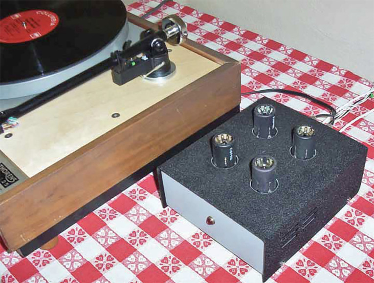
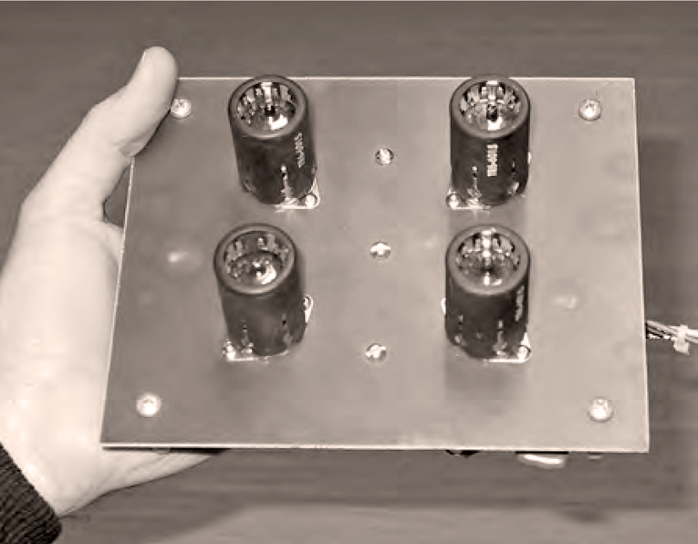
Photo 3 shows my preamplifier in its current modified state, still on the same piece of copper-clad PC board material as the original with the same phenolic tube sockets. I have changed nearly every other component. All connections on the board are component-to-component, with the copper cladding forming an excellent ground plane.
Power Supply
At the moment, I’m using a tube-regulated Gen-Rad laboratory power supply from the 1960s, which is especially nice because it’s not mine (thanks, Chris). It provides very well regulated 300V B+ and 6.3V filament supplies, both of which are essential if you don’t plan any further power-supply decoupling. The preamp draws 60mA from the B+ and 1.2A for the filaments. I included a 1nF silver-mica capacitor inside the preamplifier as a precaution to shunt any rising impedance at RF due to stray inductance in the B+ power supply umbilical, but it worked just fine without it.
Measured Specs
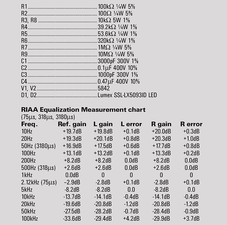
The actual measured frequency response of the preamp is indeed very flat; I didn’t need to do any empirical tweaking of the calculated circuit values. The low frequency response is about 1dB underdamped from around 20 to 50Hz, which is likely due to the presence of three capacitors within the second stage feedback loop. My rationale for this design choice is that I preferred the sound with this configuration; maybe it’s because both blocking capacitors are subject to negative feedback. Stability is ensured regardless because the amp runs open loop at VLF.
At 20kHz the response is down a little over 1dB, but it starts to rise again, becoming underdamped by 4dB at 100kHz. This is probably due to the negative feedback loop as well; in this case, an HF pole at the grid of the second stage interacts with an output pole caused mostly by stray capacitance imposed by the test equipment and interconnecting cables, which should be similar to conditions encountered in actual use. In the middle of the passband, where it really counts (my use of Edgar midrange horns reinforces my strong belief in this philosophy), the response is flat from 200Hz to 5kHz, with only a 0.1dB crest at the 75μs RIAA turnover point. This is certainly flatter than my (pretty darn flat) speakers. Gain measured 41.2dB in one channel and 41.3dB in the other, and the “A”-weighted noise with inputs shorted is -76 and -75dB, respectively, referred to a typical moving-magnet input level of 4mV. Subjective noise level is negligible; even at very high volume levels, I hear nothing when switching from CD to LP.
Listening & Conclusion
How does it sound? Well, if a meteor were to crash through my roof and wipe out my entire system, I’d spend the insurance money on parts to build another preamp exactly like this one. But seriously, folks... I believe this is about the best I can do. My friends really seem to like it, too — and some of them have very expensive tastes in audio gear. For those who can’t afford to build something quite this exotic, there’s a much cheaper version of the circuit that sounds almost as good. But that’ll have to wait until next time. aX
Thanks
Many thanks to my father Tony Tritschler, an exceptional audio engineer and loudspeaker expert without whom I wouldn’t have a system at all; to Duke Fecteau, Bob Jones, Larry Mehal, Curtis Welch, Fred Garber, and all my audio buddies for good times and invaluable feedback; to Roger Hughes at Midwest Surplus Electronics in Fairborn, Ohio, who has been taking IOUs and giving me good-natured grief for almost 15 years now; and to Chris Ivan, a first-rate tech and tremendous source of knowledge from whom I’ve stolen almost all of my electronic components, and whose hi-fi system I’ve shamelessly imitated almost entirely.
These two articles were originally published in audioXpress, October 2003 and January 2010.
Readers wishing to buy and download any specific issue from the archives of audioXpress can go here:
https://cc-webshop.com/collections/archives-audioxpress-issues-pdfs
If you would like to have the aX Cache, your own private lockbox filled with easily accessible audioXpress content go here:
https://cc-webshop.com/products/ax-cache
The aX Cache contains every audioXpress issue from 2001 to the latest issue in PDF format, on an easy-to-use USB.