The design process is pretty simple. It starts with the designers defining what they want to accomplish in terms of maximum sound pressure level (SPL) and system f3. Use Figure 6 or Equation 18 (both from Part 2 of this article series, audioXpress August 2023) to determine the driver size needed to meet the design requirements. Then substitute the f3 and driver size into Equation 24 to plot the options for box size versus input power that can realize the design. Designers are theoretically able to choose any box size they want, the only constraint being that smaller boxes require more power.
The design example will be for a system that would be a good solution for a normal domestic living space. An f3 of 30Hz is low enough to capture the majority of music content, and a maximum SPL of 105 dB is loud enough to have satisfying peak levels in a mid-sized room. Looking at Figure 6 (Part 2 of this article series, audioXpress August 2023) we see that the curve for an 8” driver passes through the intersection of 30Hz and 105.3dB, so it is the smallest driver size likely to meet our needs. Based on this we have:
f3 = 30Hz
SPLM = 105.3dB
d = 8”
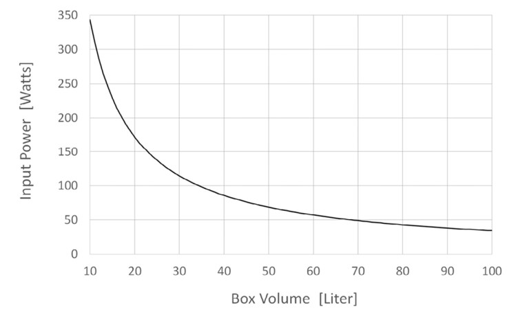
We can now substitute f3 and d into Equation 24 to see our options for box size and input power.
Doing so results in the plot depicted in Figure 7. The plot shows that we can choose any box volume we want, but that as the box gets smaller, the input power goes up dramatically. This is the real-world manifestation of The Iron Law. Our design is nearly complete. If we say we have 175W available (171.6 to be precise), we can choose a 20-liter box and the system is well quantified. We just must figure out the port. We can pick the port diameter visually from Figure 4 from Part 2 of this article series (audioXpress August 2023), or we can rearrange Equation 14 to solve explicitly for the port diameter as:
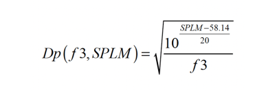
Inserting 30Hz and 105.31dB (the exact value from Equation 18) into Equation 25 yields a required port diameter of 2.76”. This is the minimum port diameter that can support our system requirement with a maximum port air velocity of 20 m/s. A larger diameter port is always possible, but a smaller diameter port will limit the maximum system SPL per our assumptions.
The last thing we don’t know for our quick design is the port length. We know that a requirement of the B4 alignment is that the box tuning frequency equals the f3 equals the driver resonant frequency (fb = f3 = fs). The equation for calculating the length of a circular port is:
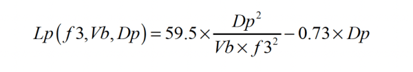
Where: Lp is port length in inches
Dp is port diameter in inches
Vb is box volume in m3
Applying Equation 26 to our system, we arrive at a port length of 23.2”. The overall proposed system is then:
8” driver
2.76” diameter × 23.2” long port
20-liter internal volume box
f3 of 30Hz
Maximum SPL of 105.3dB
172W of input power required
That would be the basis for a pretty good system! But there are still some things we don’t know, which would fall under the category of practical considerations. Can we fit the port in the box? We know the driver size and f3, but we don’t know the driver’s required Thiele-Small (T-S) parameters. Note that every combination of f3, SPL, and Vb for a given driver size requires different T-S parameters. Our design was based on a target performance, not a given driver. The driver required to match that performance has yet to be defined.
Practical Considerations
The first practical consideration is if the port will fit the box. Equation 26 tells us that the port must get longer as the box gets smaller to maintain the tuning. It makes sense that there must be some box volume below which the port will be too long to fit inside the box.
There is no universally accepted relationship between box volume and how long of a port will fit, so we will create our own. Conventional designs usually have the port opening on either the front or rear panel. If the box were a cube (not generally a good idea), each dimension would be the cube root of the box volume. So, a good starting point would be to say the maximum port length is the cube root of the box volume. But the inside of the port must clear the back wall of the box, and one port diameter of clearance is usually recommended to avoid air flow problems. So, this says that a good estimate for the maximum port length is the cube root of the box volume minus one port diameter:
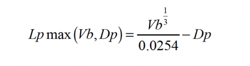
Where: Lpmax is the maximum port length in inches
Vb is box volume in liters
Dp is port diameter in inches
If we set Equation 26 and Equation 27 equal to each other and rearrange we get:
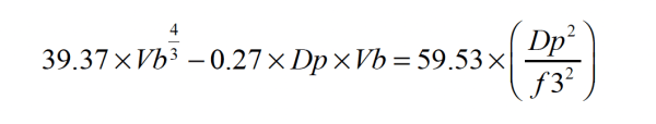
Solving Equation 28 for Vb will tell us the smallest box volume that will fit our required port length. In our design example, we had an f3 of 30Hz and a port diameter of 2.76”. Subbing these into Equation 28 and solving for the box volume gives Vb as 0.0397m3 (39.7 liters). Note that Equation 28 has no simple algebraic solution, so we must use an iterative solver. Fortunately, we will have this at our disposal when we get to the spreadsheet (which can be found in the Supplementary Materials section of the audioXpress website.)
In our design example we chose a 20-liter box, and it required a 23” long port. Equation 28 tells us that this combination is not going be to very realizable if we want to use a conventional design. The port will be too long to fit in the box. We can therefore use Equation 28 to inform the decision we make when choosing the box size and power from the equivalent of Figure 7 (or Equation 24 from Part 2, audioXpress August 2023) for any given design.
We are always free to choose a box volume larger than the limit imposed by Equation 28, and we can meet our f3 and SPLM goals. Choosing a box size smaller than Equation 28 says we will either have to:
A) Use a smaller diameter port to maintain the tuning and preserve f3, sacrificing SPLM.
or:
B) Use a shorter port to maintain the SPLM, forcing f3 higher.
Neither of these options lets us meet our performance target if we choose a box smaller than Equation 28 recommends.
If you compare the driver size, box volume, and port diameter this paper recommends to commercial systems, you’ll see they typically use a smaller port than recommended. This will limit the maximum system SPL to less than it might otherwise attain. Given the choices, it probably makes sense to go with a smaller diameter port to reduce the box size and accept that at loud volumes the port will limit the system. Ports don’t instantly stop working at our assumed maximum of 20m/s air velocity, and the onset of compression and distortion is usually gradual. A smaller than recommended port is probably the best option for shrinking the box size if a port is used, but it does have a performance cost!
Going back to our design example, we’ll replot Figure 7 with the box volume we found by solving Equation 28.
The vertical line shown in Figure 8 represents the 39.7-liter box volume that we determined to be the minimum box size that would fit the required 2.76” diameter port and tune the box to the required 30Hz. Choosing a box smaller than this will impact the performance if we use a port. However, if we use a passive radiator (PR), we can overcome the port limitations and open-up the design space to the left of the vertical line.
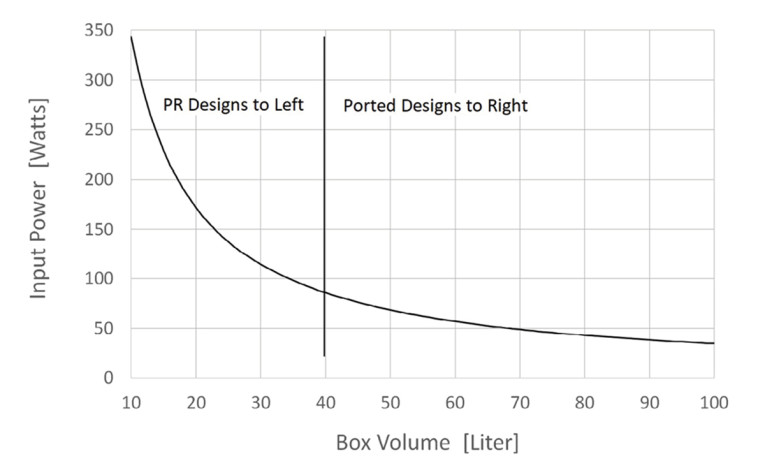
Power is cheap in the modern world, and drivers capable of handling peaks of a few hundred watts are not unusual or exotic. Our original goal of a 20-liter box volume would make for a reasonable large bookshelf design with really good performance for the category. Figure 8 says it’s very doable with a PR, but not with a port.
What price do we pay if we decide to use a 20-liter ported box in our example and either: A) use the biggest port that will fit in the box while tuning it to 30Hz; or B) maintain the maximum SPL but change the port size such that we achieve the lowest f3 while maintaining the SPL?
A) To figure this out we must solve Equation 28 with Vb and f3 as the knowns and Dp as the unknown. Doing so gives:
Vb = 0.020 [m3] f3 = 30.00 [Hz] Dp = 1.76 [in] SPLM = 97.5 [dB]
The port diameter decreases by a full inch! The new box and port size are both reasonable. We can assess the impact on the maximum SPL by turning to Equation 14 to calculate the maximum SPL that a 1.76” dimeter port can produce with an f3 of 30Hz. Doing the calculation gives 97.5dB. So, our decision to decrease the box from 40 liters to 20 liters has cost us 7.8dB of maximum output (105.3-97.5).
B) In this case, we would turn to Equation 25 to find the port diameter as a function of f3 with our value of SPLM at 105.31dB. Substituting Equation 25 for Dp(f3) into Equation 28 and iterate for the box volume as a function of f3 gives an f3 of 40.7Hz for a 20-liter box. Equation 26 gives the port length as 8.3”.
Vb = 0.020[m3] f3 = 40.74[Hz] Dp = 2.37[in] SPLM = 105.3[dB]
So, if we want to keep the SPLM of 105.3dB when we shrink the box to 20 liters we have to raise the f3 from 30Hz to nearly 41Hz.
The two analyses show how to determine the impact of shrinking the box size while still using a port. Again, assuming access to a “good” PR that won’t limit the performance, we could shrink our example box to 20 liters with a PR while maintaining the f3 and SPLM.
Driver Requirements
We already made a few basic assumptions about the driver. In this example, it is assumed that the user has specified a driver diameter (d), a voice coil resistance (Re), and a box size (Vb). The development of the equations assumed no voice coil inductance (Le), a box loss of Qbl=7.0, and a driver mechanical Q of Qms=3.0.
The B4 alignment requires enough other things to uniquely define the driver required to meet any combination of f3, SPLM, and box size. The relationships that define the driver are as follows:
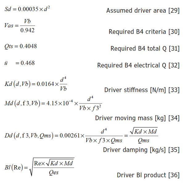
Substituting the listed values into the ported modeling program will result in a system with a B4 frequency response.
Spreadsheets
A series of spreadsheets built with Excel 2010 accompany this article and can be found in the Supplementary Materials section of the audioXpress website. The spreadsheets are described as follows:
100Hz B4 Model.xlsm: This is a version of the Vanatoo Thiele-Small (T-S) ported loudspeaker model that uses a fourth-order Butterworth alignment (B4). It is intended to let the user see the basic response shape of a B4 system. It is password protected by default.
General Purpose Ported T-S Loudspeaker Model.xlsx: This is basically the unlocked version of the above spreadsheet that lets the user modify inputs to model any ported system. Only certain cells are unlocked by default to keep the user from inadvertently changing parameters that should be fixed. But the password is included for those willing to take the risk.
General Purpose PR T-S Loudspeaker Model.xlsm: This is the Vanatoo Thiele-Small passive radiator model. Only certain cells are unlocked by default to keep the user from inadvertently changing parameters that should be fixed. But the password is included for those willing to take the risk.
SPLM vs f3 and Power vs Vb for Ported B4 System.xlsm: This is from the heart of the article. Macros must be enabled to run this model. The first tab of this model lets the user pick a driver size and f3 from a duplicate of Figure 6 and Equation (18). The minimum box size to fit the recommended port diameter is solved iteratively using Excel’s “Solver” routine (that’s the required macro). The driver requirements are calculated, and the results are then automatically loaded in the second tab of the worksheet so the user can see the modeled results. Enjoy exploring your options.
Project Files
To easily download the spreadsheet files, visit the audioXpress Supplementary Material section.
This article was originally published in audioXpress, September 2023
Click here to read: Bass Reflex Performance Envelope - Part 1: The Foundation
Click here to read: Bass Reflex Performance Envelope - Part 2: System Analysis