This is a semi-technical article intentionally written in a conversational style to tell its story. You might need to be an engineer to dig into the underlying math and challenge the assumptions, but the intent is that you do NOT need to be an engineer to understand the conclusions and the point of it all. If you know what “frequency response” means, and you know that all devices have physical limits, you should be able to follow the argument and understand the conclusions.
When confronted with a clean sheet, loudspeaker designers must ask themselves “what’s possible?” While overall sound quality is what defines a system, the bass response is typically what dictates the size, power requirements, and a good deal of the cost of a loudspeaker system. This paper will look at a subset of designs typically possible from a “bass reflex” loudspeaker.
The results can be used by the designer to quickly home in on what’s possible, and to define the requirements for a proposed system. The results can also be used to “reverse engineer” an existing design to know what to expect. This article also shows which bass reflex designs can be realized with a ported cabinet versus the family of very attractive design options that are only realizable with a passive radiator design.
The Basics
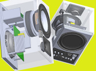
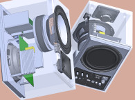
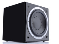
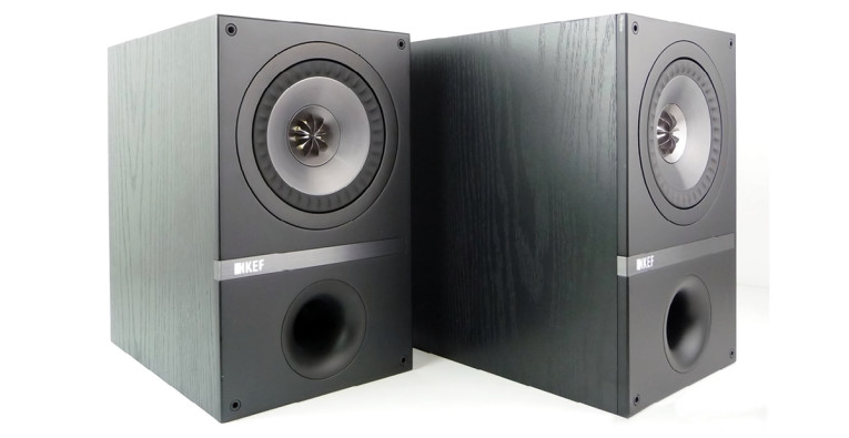
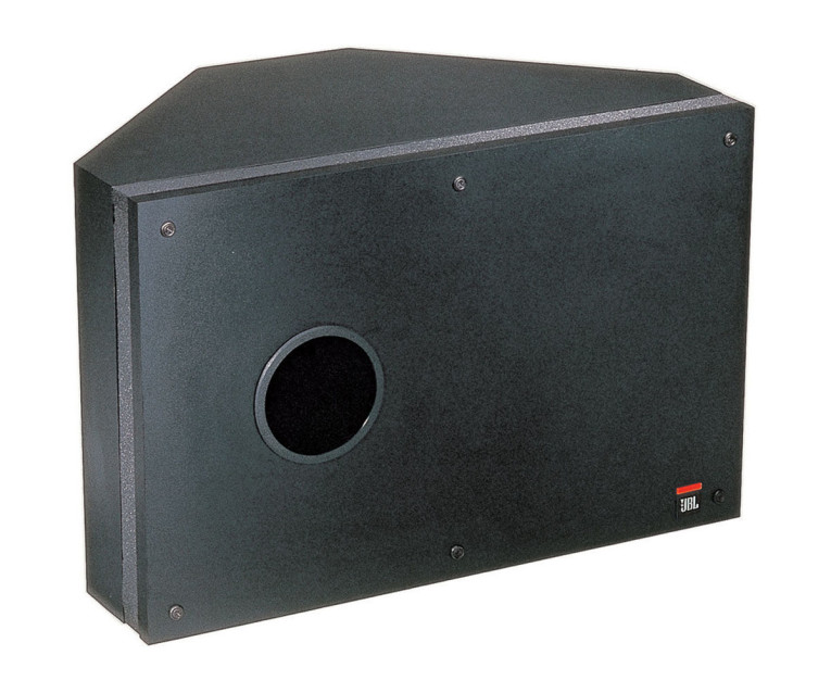
“Bass Reflex” is sort of an old-fashioned term that was applied to what today we more typically call ported or vented speakers (Photo 1). I’ve chosen to use the term here since I think it evokes the sort of working action shared by both ported and passive radiator speaker systems and can be used as a single term to cover both. A bass reflex system is one in which another moving element is added to the speaker enclosure in addition to the driver. This element, be it the mass of air in a port or the diaphragm of a passive radiator, is driven by the air pressure in the box (Photo 2). When properly constructed, the additional moving element will resonate at a lower frequency than the driver and effectively help extend the system’s bass response. While “resonance” is typically considered a dirty word in audio, a well-designed bass reflex system can have tight, articulate bass that is very satisfying to even the most critical listener.
A ported system is one that typically has a tube inserted in the cabinet such that air can flow in and out. Sometimes a slot is used instead of a tube, and for the most part the exact shape of the opening is of secondary importance. The important thing is that there is a slug of air that is defined by the dimensions of the port, and this slug of air has a known mass. When the air in the port moves into the box it compresses the air that is already inside, increasing the pressure, which wants to force the slug of air back out of the box. The compressed air in the box therefore represents a “stiffness,” or spring.
The Helmholtz resonance of the port and box is what a bass reflex speaker uses to extend the bass a speaker might otherwise possess. The in-and-out motion of the driver produces pressure in the box, which drives the in-and-out motion of the air in the port. Each of these vibrating ”surfaces” produce sound. The visualization of how these add together in our system is shown later, but the design trick is to get these two sound-producing mechanisms to blend together seamlessly.
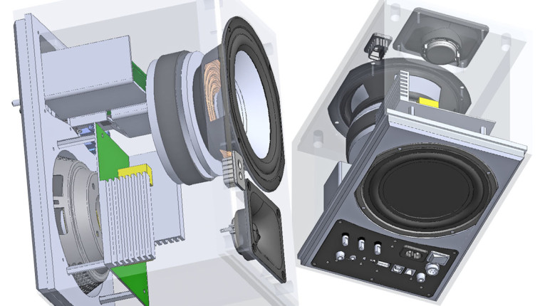
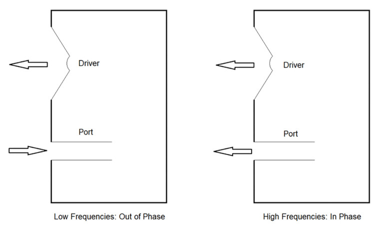
Figure 1 shows the cross-section of a ported bass reflex. At low frequencies the outward motion of the driver creates a vacuum in the box, drawing air in through the port. As the frequency increases to the Helmholtz resonance and above, the moving air in the port can no longer keep up and starts to lag the cone motion. At higher frequencies the air in port has enough inertia that it moves very little, and the lag is great enough that it is effectively in phase with the motion of the driver.
Albert L. Thuras was issued the original patent for this type of system in 1932. It wasn’t until the 1960s (Albert Neville Thiele) and 1970s (Richard Small) until the behavior of the system was thoroughly defined mathematically. The Thiele-Small (T-S) model of bass reflex loudspeakers shows how to properly configure the driver, box, and port such that the overall sound generated by the port and the driver blends together in a predictable and desirable manner. The widespread adoption of the T-S model and the success of systems designed using it is responsible for the explosion of high quality (if often somewhat similar) ported systems on the market today.
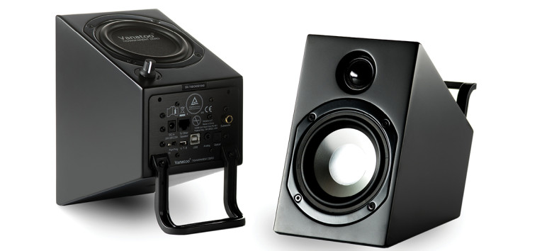
At this point, it is worth noting that a passive radiator, which often just looks like a driver with no magnet or motor, works almost identically the same as a port. This also describes its behavior, and both can be considered “bass reflex.” The primary advantage of a passive radiator is that it allows a lower Helmholtz frequency in a small box than can be achieved by a port. This means deeper bass from small boxes, which is why Vanatoo incorporates passive radiators in its Transparent line of powered speakers (Photo 3).
Response Types
Thiele, Small, and most of the pioneers of loudspeaker design were electrical engineers. Different ways of filtering electrical signals were a hot topic in electrical engineering in the early 1900s, and a lot of different filters with different response types were developed and documented. Thiele recognized that a bass reflex speaker is analogous to an electrical high pass filter, and that if he looked at its behavior from the right mathematical perspective, the already well-developed theory of electrical filters could be used to describe a speaker’s behavior.
Thiele defined different ported speaker “alignments” that would cause a speaker’s response to match one of the already well-known electrical filters and generated a set of design tables that showed how to build such systems. A decade later Small extended Thiele’s work to include boxes with losses, more alignments, and other useful insights. While a speaker is not required to match any known filter, doing so meant you understood its behavior at a time when no engineer had a computer on their desk!
This article will concentrate on just one of the infinite possible responses: The Fourth-Order Butterworth high-pass response (or “alignment”). The Butterworth response is chosen for several good reasons. It is arguably “the best” of all possible responses because it typically has the lowest -3dB frequency of any system that has a “flat” frequency response without humps or ripples. The Butterworth design also requires that multiple design parameters be precisely related mathematically, which allows the analysis to be reduced to some simple yet powerful relationships. While it might be possible to have higher output or lower f3 than this model predicts with a different “alignment,” the results of the Butterworth analysis should be indicative of bass reflex in general.
The Analysis Approach
The approach taken in this analysis pulls together a lot of different pieces from loudspeaker design and acoustics to tell its story. It starts with limiting the scope to systems with a Butterworth response. It shows that if you have a ported system with a Butterworth response, you don’t need a lot of other constraints to really understand the system. If you know the system’s -3dB frequency (f3), you already know the frequencies that limit the maximum sound pressure level (SPL) the system can produce.
If you know the size of the driver based on the currently popular sizes on the market (4”, 8”, etc.), you can make a reasonable estimate of the system’s maximum SPL. The port is defined as being big enough to keep up with what the driver can deliver in terms of SPL. The relationship between box size and power is developed, where it is shown that the designer is theoretically free to choose any box size. The box size and port that will work best for the chosen design are defined. Lastly the requirements that the design places on the driver are defined.
Assumptions
This analysis is going to apply the T-S model to a Fourth-Order Butterworth system (B4 from now on) and assume that the model can predict when the system reaches its physical limits. Experienced speaker designers will know that T-S is a “small signal” model and is not generally considered valid at large amplitudes. There are newer models than T-S that include the effects of the speaker parameters varying with displacement and current in a nonlinear manner, but they are messy and complicated. We know that the linear T-S model isn’t really valid at the larger amplitudes that we are going to encounter in this analysis, but it is better than throwing our hands up and saying we don’t know anything. In the author’s own experience, the driver stiffness (and PR stiffness if one is employed) is the parameter that changes most with large excursions.
Drivers tend to look about 50% as stiff when driven to their Xmax than they do when measured in the small-signal domain. Reducing the driver stiffness by 50% in the model shows that in most cases the overall results aren’t changed dramatically. The maximum SPL is typically reduced by about 3dB when the stiffness drops by 50%, with all the trends remaining the same. The sum of the nonlinear effects means the system won’t really behave like our model at its limits, but the overall behavior will be close enough to make the analysis worthwhile.
An assumption of the T-S model is that the driver is mounted on an infinite wall, radiating into half-space. This becomes important when we get to the part of the analysis where we consider how much power is needed to drive the system.
We are going to assume specific relationships between a driver’s advertised size and its cone area (Sd) and maximum usable displacement (Xmax). Neither one of these relationships will match many real-world drivers exactly, but in the author’s experience they represent good averages of what is currently available in high quality hi-fi drivers. We will also assume a few other details about our driver and port.
Next Article
In Part 2 of this three-part article, we will answer the question of what determines how loud and how low a system will play, how that relates to generally available drivers, and make the observation that box size is entirely up to you. aX
This article was originally published in audioXpress, July 2023
Click here to read: Bass Reflex Performance Envelope - Part 2: System Analysis
Click here to read: Bass Reflex Performance Envelope - Part 3: A Practical Example