
Author’s Note: A few times references are made to equation derivations from books that are no longer available on the market. They were written in the heroic days and 20 years ago. We make these derivations available in the Supplementary Material section of the audioXpress website (see the Project Files link). As a rule, these mathematical derivations are “unfriendly,” if not offensive.
Introduction
In the past century a lot of knowledge on the operation and design of tube circuits has been developed. Please realize that in the years 1945 to 1965 there were tubes only (“them phony transistor things” were not yet appreciated by everyone). After the decline in the use of tubes, replaced by the much more powerful and easier to handle transistors (you cannot drop a tube and go unpunished; you can drop a transistor), this knowledge has partly been forgotten.
But you don’t need all this ancient knowledge to create a reasonably good tube circuit design. There are several good books and articles out there. However, it can be observed that from time to time statements are made by designers that are wrong. I have already mentioned two of them.
The first one refers to the so-called load match. For instance, output stages use an output transformer that has to fit the behavior of the output tubes. It usually does not do this completely. This is often marked as bad, but this opinion is not well founded. I will explain.
There are two excellent reasons to choose impedance mismatch. The first one is you happen to have a transformer and you are willing to use it. A load mismatch will result in a small loss of output power. Fact of the matter is that most likely you will not hear this small difference. The second reason is that you can choose mismatch in order to reduce distortion. This proves to be an extremely efficient weapon.
What Is Load (Mis)match?
Figure 1 shows an ECC82 (12AU7) circuit that you probably have seen many times.
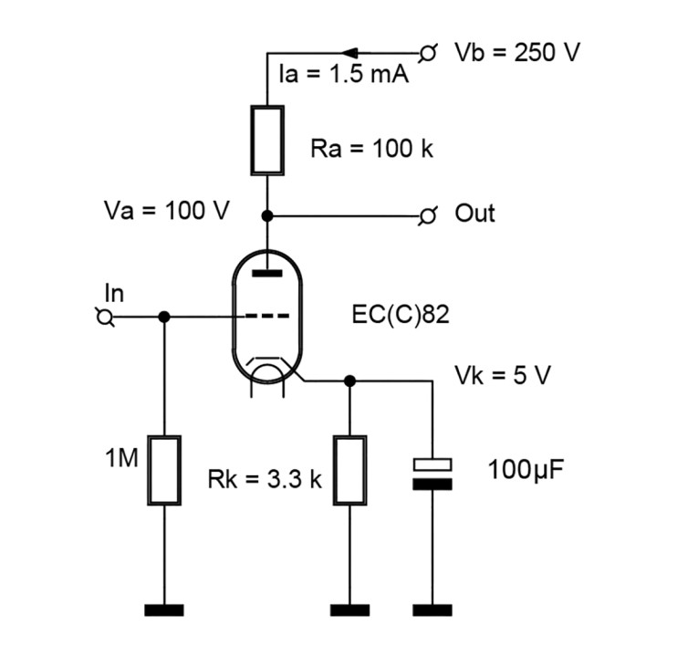
The supply voltage is Vb = 250V. The anode resistance Ra is 100kΩ. The chosen current is 1.5mA. Therefore the anode voltage is Va = 100V.
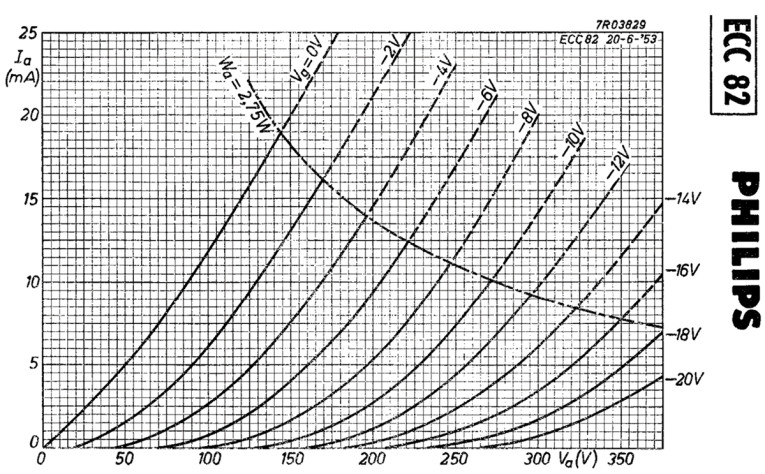
According to the characteristics shown in Figure 2, an anode voltage of 100V and an anode current of 1.5mA indicate that we need a cathode voltage of Vk = 5V, and hence the cathode resistor has a value Rk = 3.3kΩ. The cathode resistor is decoupled with an electrolytic capacitor (i.e., an elco) of 100µF.
Now look at the voltages shown in Figure 1. During the positive part of a sine wave input signal, we can pull the anode voltage down to 40V, assuming that we want at least 40V across the triode (neglecting Vk). This is an AC negative peak voltage of va = (100 – 40) = 60V.
During the negative part of a sine wave input signal the anode voltage can rise up to as much as 250V (the pinch-off situation of the triode). This is a positive AC peak voltage of v = (250 – 100) = 150V. There is a large asymmetry between the two signal parts. You may call this non-symmetrical, non-optimal or a mismatch.
Changing the current to 1mA would result in an anode voltage of Va = 150V. This requires a cathode voltage of 9V, and therefore a cathode resistor of 9kΩ. We could then make a positive va swing of 100V and a negative one of also 100V, where Vk = 9V. Now this is symmetric and there no longer is a mismatch. The AC swing at the anode now is 200Vpp.
The question is whether this is a better design. When we want to output a signal of 200Vpp, it definitely is. When we want to amplify a microphone signal in the millivolt world, both circuits would do.
Thus, matching and mismatching do not exist in themselves, but they depend on the usage of the application. There is no such thing as an optimal match in itself. The concept of matching implies at least two actors.
Operating Points of Output Triodes
A First Design
Instead of discussing things, it is better to just design an output stage here and conclude a few things from the results. The whole purpose of a good output stage design is to pull as much power out of the tubes as possible. In this instance, we will use an EL34 (6CA7) as an example. However, our design freedom is limited by a few maximum values of the tube.
This EL34 tube is a pentode. It can be dressed as a triode by connecting G2 to the anode. Also G3 can be connected to the anode. With a 6L6, you can’t because its G3 is internally connected to the cathode.
In forum discussions, we see opinions whether to connect G3 to the cathode, as usually it is the case with pentodes, or connect it to the anode.
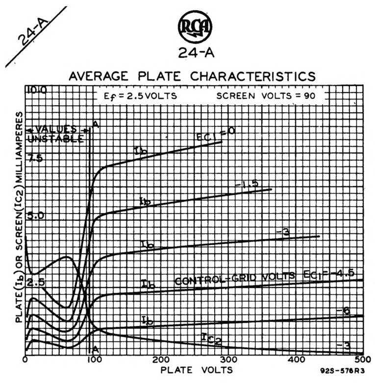
A tickling question is what made the EL34 designers decide to make G3 available on pin 1? The answer is, that a separate G3 connection is needed when not wanting to have the tetrode behavior (Figure 3), but the pentode behavior instead.
The physical distance between G2 and G3 is small. Therefore a maximum value of Vg2 is specified.
A too high voltage on Vg2 connected to the anode, where G3 has cathode potential, may result in sparks. You would not want that. In our case, we don’t have tetrode behavior, therefore, we do not need the healing influence of G3. Let us lump all metal beyond G1. In a pentode configuration, Vg2 will not get that large anyway—usually is it fixed with an elco.
These characteristics, shown in Figure 4, are constructed by myself from earlier less readable graphs. I apologize for not giving the needed scientific credit. I do not know where I got this early material 25 years ago.
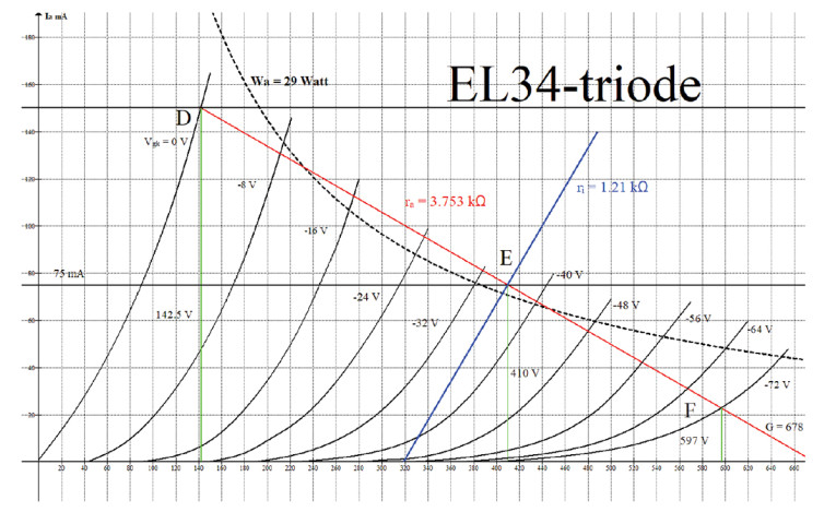
Step 1: Choose a dissipation and a quiescent Vak voltage. I have chosen Vak = 410V and Ia = I0 = 75mA. This is a common choice. The quiescent point E is where, in Figure 4, the red, the blue, and the green colored lines intersect. The power consumption is Pa = 410 × 75 = 30.75W.
The specs (see the EL34 datasheet [1]), say Pa <= 24W and PG2 <= 8W. This adds up to 32W. But be careful, it is not guaranteed that with an anode current as given, that when the anode dissipation is 24W, the G2 dissipation is less than 8W. I have chosen to limit the sum of these dissipations to 29W. The 30.75W would be somewhat larger than my chosen maximum for the EL34 triode, so this configuration may not be on the safe side. For the reasoning here, this is not relevant.
Step 2: Now the tube’s anode current can drop from I0 to zero. In a Class-A configuration, it can increase to 2 × I0. This maximum value of course is reached when Vg = 0. This maximum current, according to the specs [1], is 150mA. The red load line, shown in Figure 4, is drawn from the point
(410, 75) toward a current of 2 × 75 = 150mA. The point D of 150mA is chosen where the red line crosses the curve of Vg = 0.0V in the point (142.5V, 150mA). Extending it to the right side, it happens to hit the Ia = 0 line at point G, where Va = 678V. We now know two values: the anode voltage swing is
va_ = (410-142.5) = 267.5V. The anode current swing is 75mA. But we can tell a lot more.
The power consumption is Pa = 410 × 75 = 30.75W. The power transferred to the output transformer is:
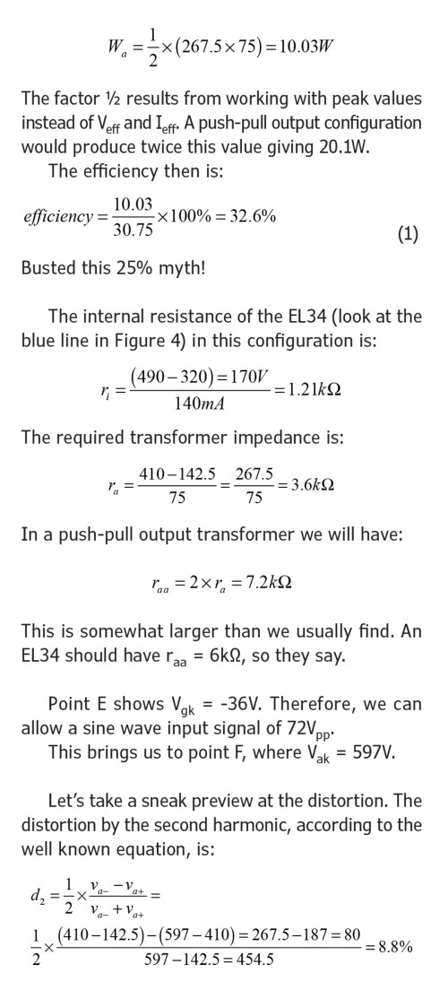
In the nominator, we find the difference of the two anode signal half swing values. In the denominator we need the full swing value. The distortion is 8.8% when vaa = 454.5Vpp.
You may find this distortion a bit too large. It will be shown in the sequel that this distortion will be nullified.
A Second Design
The design shown in Figure 5 has a lower power consumption. Its Va = 344V. Its I0 = 70mA.
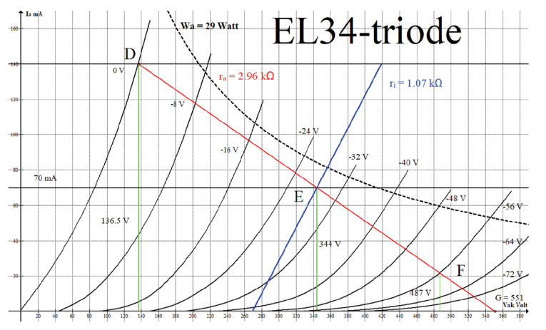
We can repeat all calculations: The red load line is drawn from the point (344, 70) toward the point D with a current of 2 × 70 = 140mA. Extending it to the right side, it happens to hit the Ia = 0 line at the point G, where Va = 551V. We now know the anode voltage swing is va = (344 - 136.5) = 207.5V. The current difference is 70mA. The power consumption is Pa = 344 × 70 = 24.08W. The power transferred to the output transformer is:
Using an Existing Transformer
In the previous design, I chose the quiescent anode voltage and derived the corresponding ra.
If your existing transformer is designed to provide a specific ra , just change the order of things.
Choose the maximum value of Ia = 2 × I0. Observe the corresponding Vmin in point D (Figure 4).
Now take V = R × I or, va = ra × I0. Add this AC peak value to Vmin and you will have the required value of Va and Vb.
A Mathematical Model of a Class-A Triode
There is a lot of theory on the configurations of triodes. The needed theories are not derived here. The derivations can be found in [2], [3], [4] and in the Supplementary Material section on the audioXpress website or in one of the better books.
The equations cited here give:
A triode in a balanced push-pull output stage in Class A has an optimal so-called power match when ra = 2 × ri and thus, in a balanced stage raa = 4 × ri. The maximum AC peak anode voltage is half the Vak value.
This last equation is quite unknown. Pa is the anode dissipation for the triode. Wa is the power transferred to the transformer and thus to the loudspeaker. These values combined give us the efficiency.
So, the triode’s efficiency also has a maximum of 50%, just like the pentode. This is in contrast to what is often published, and I have already busted this myth. We approach this maximum efficiency by combining a high value of Vak and a triode with a low ri.
Putting two triodes in parallel to get half the value of ri does not solve a thing because the value of Pa between the two parentheses doubles. The product of Pa and ri remains the same! We really need a triode with a low ri by design.
We can now substitute the values found in
Figure 5 into Equation (4) and see what we get:
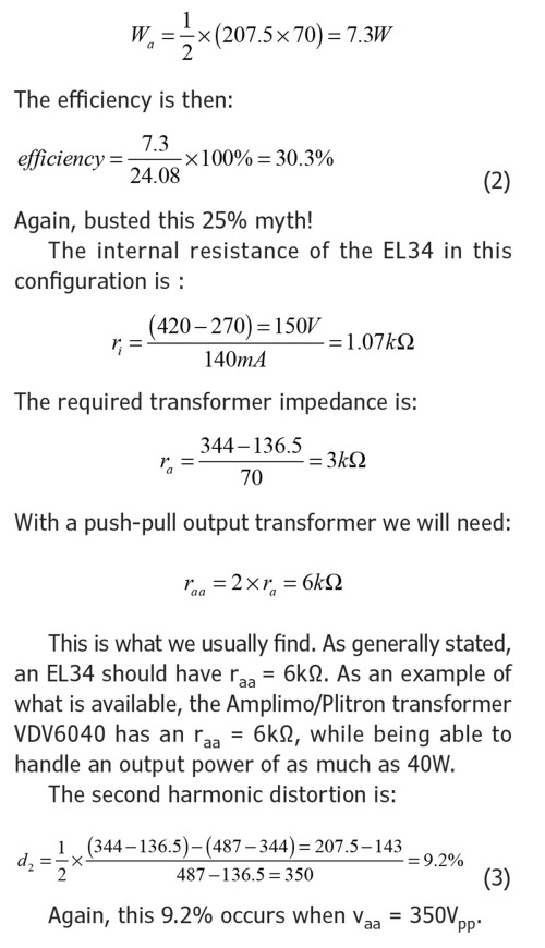
Working with the characteristics, which is always more accurate than any model, we saw that the efficiency was 30.3%.
For ra we found ra = 3.0kΩ and for ri we found ri = 1.07kΩ. The theory said ra = 2 × ri .The va swing should have been va = ½ × Va or, 172V. It is 207.5V. The conclusion is that the theoretical model is not that sound. It is derived from an idealistic representation of the curves from the characteristics. Stick to the approach of working with the characteristics; they are always correct.
The Influence of Mismatch on the Distortion
Cancelling Out Even Harmonics
First of all, balanced output transformers have a beautiful, unexpected property. Most designers know that the magnetic fields caused by the two DC anode currents cancel out each other.
What is less known is that they also cancel out the even (second and fourth …) harmonics. They add up the odd harmonics. A triode produces mainly even harmonics, which sound as octaves of the fundamental. After the cancellation, there is only minimal distortion left. This is the strong card for triodes when we want a low distortion. The price is a lower efficiency.
The Influence of Ra/ri on Distortion
There are two less known equations about the influence of the ratio Ra/ri on distortion. Once more, these theories are not derived here. The derivations can be found in [2], [3], [4] or on the audioXpress website or in one of the better books.
These equations are:
In these equations d2 and d3 are respectively the second and the third harmonic distortion levels when Ra = 0. (In this situation, we can measure the distortions in the anode current). These distortions are large because we deal with real triode curves. They are the results of the triode’s 3/2 power law. To convince yourself, substitute Ra = 0.
The left-hand side numbers with an accent indicate the distortions that result, after applying an anode resistor Ra. These distortions can be significantly lower.
A triode mainly has second harmonic distortion. A triode also has a low ri . The triode benefits from a large Ra; this gives a high value in the denominators of Equation (5) and Equation (6).
A pentode with its third harmonics distortion has a high ri, which is written as rp in this article. (Its name, traditionally, is plate resistance). The value of rp is usually much larger than Ra, therefore pentode distortion does not benefit from a larger Ra.
A Computational Example
To see the healing property of an impedance mismatch, at first, we take Ra = 50kΩ and after that Ra = 200kΩ. For simplicity we state that in these two cases we have the same ri = 10kΩ.
Increasing Ra results in a decrease in distortion of 441/36 = 12.25 times.
Taking a closer look, we may conclude that increasing Ra wins from the increase of ri. Unfortunately, Ra cannot be increased infinitely. When we do this, we get a too high DC voltage drop across this resistor. The anode current drops and we end up in a position in the characteristic where ri has increased. To maintain the same value of ri, we need a higher supply voltage.
The moral is that when choosing a small power mismatch, a too high ra will result in some loss of power, but at the same time in a reduced distortion. Mismatch is not bad per se.
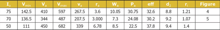
Finally, Table 1 shows the comparisons of the designs. (I added a third design with a lower current, i.e., a high ra. There is no corresponding figure for this).
Conclusions
The maximum power was obtained by extending the EL34 beyond its limits. The minimum power and the maximum differ by 73%; one can distinguish this by ear. The efficiency is always larger than 25%; so that myth is also busted. The distortion is always too large, but the even-order harmonics will be cancelled out to a large extend in a push-pull stage.
Project Files
To download additional material and files, visit
http://audioxpress.com/page/audioXpress-Supplementary-Material.html
Readers can contact the author by email here.
References
[1] EL34, https://tube-data.com/sheets/010/e/EL34.pdf
[2] P. Dieleman, Theorie en praktijk van buizenversterkers, Segment B.V. 2004.
[3] P. Dieleman, Théorie et pratique des amplificateurs audio à tubes, Segment
B.V. Elektor, 2005.
[4] P. Dieleman, Theorie und Praxis des Röhrenverstärkers, Segment B.V. 2004.
This article was originally published in audioXpress, May 2023