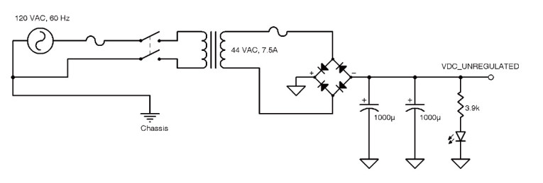
Figure 1 shows a typical unregulated power supply. Any unregulated power supply has output impedance. So as load current increases, an unregulated power supply’s output voltage drops. A linear regulator that follows this unregulated supply must have a set point at least its headroom requirement below the lowest voltage the unregulated supply will drop to under its heaviest expected load.
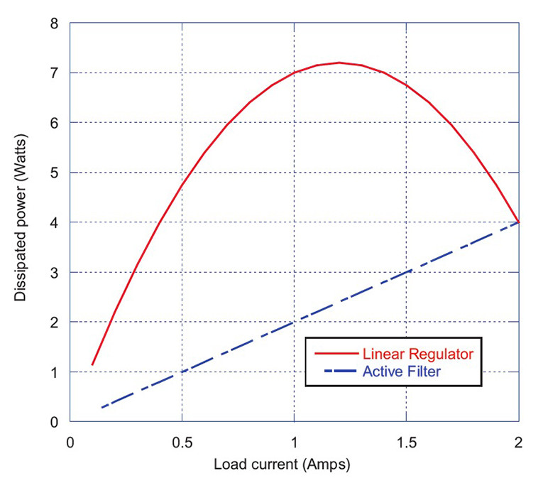
For example, the output voltage of an unregulated supply that sources 60 V under a light load typically drops below 50 V under a 2-A load. A linear regulator designed for this system may need to have an output voltage of approximately 48 V to avoid going out of regulation. Under a 1-A load, the power dissipated by the linear regulator would be approximately 7 W (i.e., 55 V – 48 V × 1 A).
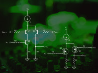
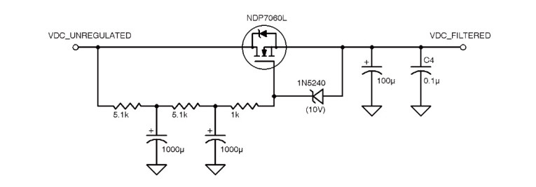
As an alternative, a source follower-based (SFB) low-pass filter provides good power-line ripple rejection while dissipating much less power—no more than 2 W (see Figure 2). Figure 3 shows a power dissipation comparison between a linear regulator set to 48 V and an SFB filter using a logic-level MOSFET with a 2-V gate source threshold. The comparison assumes that the power source is the unregulated power supply shown in Figure 1. This supply has a no-load output voltage of about 60 V and a 5- output impedance. Note that the SFB filter’s power dissipation linearly increases with the load current. (It is simply the pass transistor’s gate-source threshold voltage times the load current.) The linear regulator’s power dissipation peaks at medium loads.
How It Works
The SFB filter’s transistor acts as a source follower. Its output (source) voltage is following a two-pole, low-pass filtered version of its input (drain) voltage, so the majority of the ripple on the SFB filter’s input is rejected at its output. Unlike a negative-feedback linear regulator, an SFB filter does not hold its output voltage constant. The SFB filter’s output (source) voltage floats approximately the MOSFET’s gate-source threshold voltage below its average input (drain) voltage—minimizing power dissipation.
MOSFET power transistors with low (logic level) gate-source threshold voltages are key to the SFB filter’s low-power dissipation. Maximum gate-source threshold voltages for logic-level MOSFETS range from 1 to 2 V. Typical power MOSFETs (e.g., the IRF540N) have a threshold voltage of approximately 4 V, so power dissipation is four times as high.
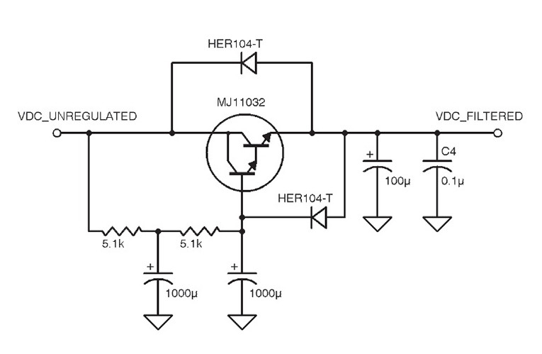
A bipolar Darlington transistor can be used to build an equivalent filter (see Figure 4). It has almost identical ripple rejection, but higher power dissipation than the logic-level MOSFET-based filter. Its output voltage floats approximately 3 V below its average input voltage.
Design Considerations
Stability and Transistor Protection — The MOSFET’s 1-k gate resistor ensures stability under the large capacitive load the filter is driving (see Figure 2). The 10-V Zener diode protects the transistor from excessive gate-source voltage when the system is powered off under load. Of course, be sure to mount the transistor on an appropriately sized heatsink.
Filter Resistor Selection — Since the two-pole RC filter’s attenuation increases at 40 dB per frequency decade, and we want to have at least 50-dB attenuation at 120 Hz, we would like to have a pole frequency at or below 1 Hz. The filter capacitors can easily be much larger than the 1,000-F values shown in the reference design.
Since this MOSFET transistor is a voltage-controlled device, large resistor values do not affect the transistor’s performance. However, bipolar transistors are current-driven devices, and the filter resistors limit the transistor’s base current. The SFB filter shown in Figure 4 uses a Darlington transistor because its high current gain (Beta) enables it to pass large load currents with limited base current. If we had used a single bipolar power transistor, we would have had to use much smaller resistors — limiting the filter’s ripple rejection performance.
Using resistors that are too large (10 k or greater) with a Darlington transistor will choke the filter’s ability to supply load current. Obviously, small-valued resistors (2 k or less) will make the filter less effective.
Output Capacitors — As with a linear regulator, the SFB filter’s output impedance increases with frequency, so the output capacitors shown in Figure 2 and Figure 4 are necessary to supply high-frequency currents to the load.
Ripple Rejection
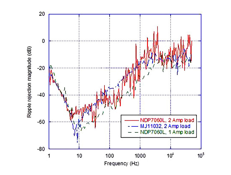
The SFB filter does not maintain its ripple rejection performance at higher frequencies. Parasitic capacitance in the filter’s high-power transistor limits the filter’s frequency response. Output-voltage-to-input-voltage transfer function magnitude measurements show the SFB filter only tracks the two-pole low-pass filter feeding its base up to about 10 Hz (see Figure 5). Above that frequency, the transistor’s frequency limitations lower the ripple rejection.
An Interesting Compromise
The SFB filter is an interesting compromise between an unregulated and a regulated supply for audio amplifiers. It provides good power-line ripple rejection with less power dissipation than a traditional linear regulator. ax
About the Author
Bill Reeve is a director at Lockheed Martin Corp. in Palo Alto, CA. He has graduate engineering degrees from the Colorado School of Mines, The University of California, Berkeley, as well as a Masters in Electrical Engineering from Santa Clara University.