Bias-Metering Circuit
This bias-metering circuit is not new by any means, but it enables quick, simple, and reasonably accurate bias setting without a meter. It is a simple, discrete transistor differential amplifier driving a pair of LEDs. When the two reasonably matched transistors’ bases have the same
voltage, the LEDs illuminate equally. If the voltages are unequal, one LED will be dim while the other will brighten. Increased voltage divergence will cause one LED to be fully illuminated while the other LED would be completely off. This way, you can see if the bias is out of adjustment with just a quick glance.
Using the comparator circuit, one transistor’s base is connected to a reference voltage equal to the voltage you want to set at the cathode resistor(s) of your output tube(s). The other transistor’s base goes to the monitored cathode resistor’s high side.
Board Design
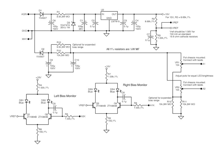
The board I designed has a pair of comparators since the Dynaco ST70 has only one cathode resistor per channel. Each resistor should have 1.56 VDC, representing 100 mA, across the 15.6-Ω cathode resistors for a pair of output tubes. The reference voltage was generated by dividing the circuit’s regulated 15-VDC supply.
Keep the lower resistor at 1 kΩ or a little less and select the divider’s upper resistor to give the desired reference voltage. The regulator can be a 12- or 15-V part, just adjust the reference divider as needed to produce the desired reference voltage (see Figure 1).
Note: Test the regulator’s output before installation and calculate the exact divider resistor values since there is some variability in the output of three terminal regulators (e.g., ±0.6 V on a 7815) and on the set point precision. Another easy alternative is to pad (i.e., parallel) one of the divider resistors with a high-value resistor to tweak the reference voltage up or down a few millivolts.
The circuit seems tolerant of parts choice. I tried random 2N4401 transistors and matched Diode’s high-gain ZTX-694Bs. I received acceptable performances in each case. But, it is best to use a digital multimeter (DMM) with a transistor gain test function to match the transistors. I also found it worthwhile to test the LEDs for uniformity using a battery or bench supply and connecting them in series with a current-limiting resistor. I found that green LEDs vary unacceptably in brightness and color shade (green to yellowish green). I chose blue LEDs since they are much brighter at low currents and more consistent in color and brightness. They also look cool.
If you have an amplifier with one resistor per tube and four tubes, use two boards with four comparators. A 20-V Zener diode protects the regulator and enables the use of lower voltage filter capacitors. I “stiffened” the bias supply with a higher value and voltage capacitors (100 μF/100 V vs. 50 μF/75 V).
Board Assembly
This board is designed to fit a ST70 chassis, but it could be fit to other chassis. The first thing to do is to ensure the filter capacitors are fully discharged! If you are using a ST70, remove all the tubes, the two bias potentiometers and their wiring, the selenium rectifier or silicon diode, and the bias supply capacitors.
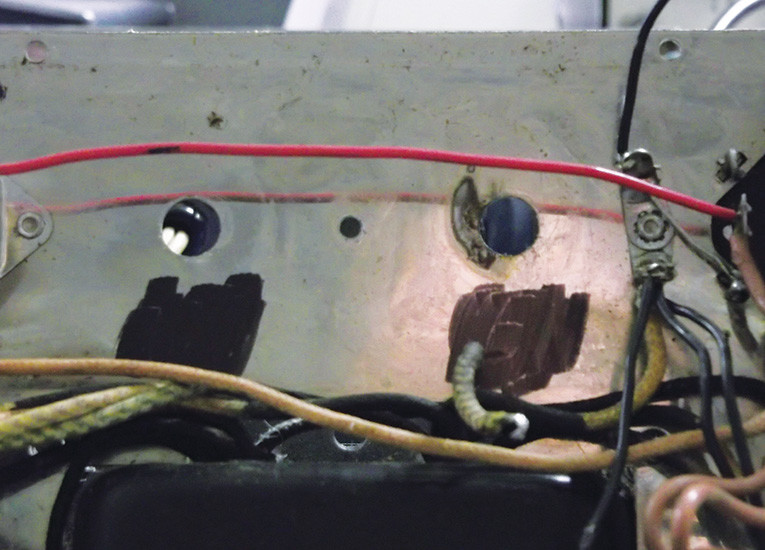
Use a black marker to blacken the chassis in the area between the potentiometer’s holes and the power transformer on the bottom side of the chassis (see Photo 1). On the bottom of
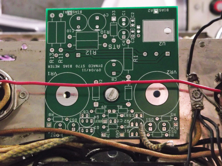
the chassis, mount the bare board with 6-32 hardware using the hole that held the selenium rectifier to ensure the board is square with the chassis. Use the two holes in the board that match the potentiometer’s mounting holes’ centers as a guide (see Photo 2).
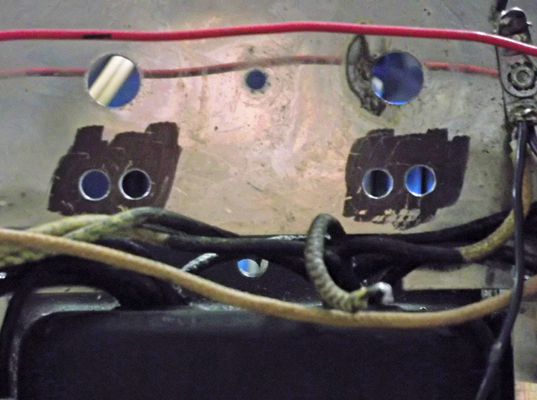
Use a needle or other sharp instrument to mark the eight LED lead holes so the marks show in the area blackened with the marker. Remove the board then carefully center punch four places exactly centered between each of the marked pairs of lead holes. Drill four holes for the LED size you want to use (T1 or T1.75). Start with a small pilot drill then enlarge the bit size to the final size or use a tapered hand reamer to get the exact size. Be sure to avoid damaging the power transformer leads (see Photo 3).
Deburr the holes on both sides of the chassis (hand turning a large drill bit works well) to ensure the LEDs fit satisfactorily. Then, clean out any metal chips that might have fallen into the chassis. The marker can be removed with isopropyl alcohol.
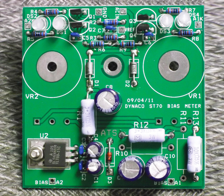
I used blue T1.75 LEDs and ground the LEDs’ ends flat for a more diffused light. I later mounted them flush with the chassis for cosmetic purposes. Install and solder all the parts on the board but do not solder the LEDs (see Photo 4). Insert them and bend their leads a little so they and lock washer to install a 7/8” long 6-32 standoff in the center hole of the board’s component side.
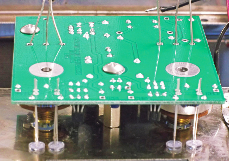
Solder bare wire leads (1.5”, 2”, and 2.5”) to the two potentiometers staggered in length by about 0.5” (see Photo 5). Mount the potentiometers to the chassis. If any of the power transformer leads are in the way of the LEDs’ holes, dress or ty-wrap them out of the way. With the board’s component side facing the chassis, tilt the board slightly. Starting with the longest potentiometer lead, thread all six leads into the matching holes in the board (see Photo 6). Secure the board’s standoff with a 6-32 screw and lock washer through the chassis’s top, ensuring that it is square with the chassis.
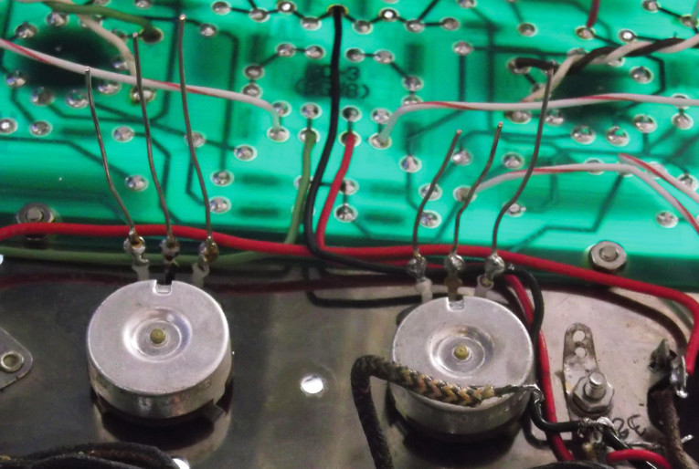
Solder the potentiometers’ leads and trim them. Then, position the LEDs in their respective holes. If you ground them flat and want them flush with the chassis, a piece of tape on the top of the chassis will hold them in place while you solder them (see Photo 6).
Refer to Photo 4 and Photo 7 for the next few steps. Solder the power transformer bias supply lead to the pad labeled ACIN. Note: All the PCB connections are labeled in white on the component side as well as in copper on the circuit side (see Photo 4). Solder a wire from the chassis ground lug to the pad labeled GND. Solder a wire from the pad labeled A1 (BIAS) to driver board pad 21. Solder a wire from the pad labeled A2 (BIAS) to driver board pad 6. Solder a wire from the pad labeled A1K to pin 8 of the output tube on the A1 biased channel where the 15.6-Ω resistor is located. Then, solder a wire from the pad labeled A2K to pin 8 of the output tube on the A2 biased channel where the 15.6-Ω resistor is located.
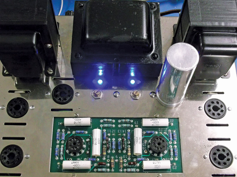
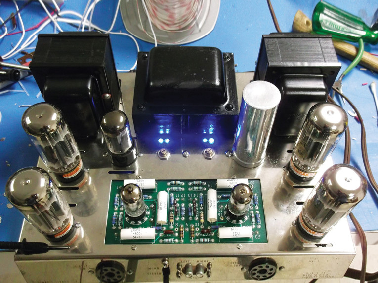
Power up the unit without any tubes installed. The two center LEDs should be brightly illuminated, indicating low current (the outer two LEDs indicate high current) as shown in Photo 8. Verify that there is approximately 1.56 VDC (or the reference voltage you selected) at the test point on the boards labeled VREF. Verify that the potentiometers produce approximately –45 VDC on each tube’s pin 5 when fully counter clockwise, and decreases to approximately –30 VDC fully clockwise.
Note: Leave the potentiometers in their fully counter clockwise positions. Failure to do so could cause severe damage to the amplifier.
Install all the tubes and power up the unit. Allow 5 to 10 min. for the tubes to stabilize. Then slowly turn each bias potentiometer clockwise until the LEDs are equally bright. Note: There will be some interaction since the bias supply is not regulated. Set one side, then the other, and then readjust the first one. Repeat as needed until both pairs of LEDs are equally bright. Initially, as an added precaution, you can monitor the bias voltage (1.56 V) with a digital volt meter (DVM) at the octal socket on the front of the chassis. After the tubes are stable and the bias current has been confirmed, just watch for equally bright LEDs (with no signal of course), or adjust the potentiometers as desired — no meter needed (see Photo 9).
Details
It may take the amplifier 5 to 10 min. to stabilize, so initially the low current (center) LEDs will be illuminated. Amplifying a signal will, naturally, indicate higher current and then the outer LEDs will be brightest. Line voltage fluctuations will affect the bias as well.
Added Options
With the corner of the chassis previously occupied by the bias supply now vacant, I added four 82-μF/350-VDC capacitors in series and parallel with two 220-kΩ, 2-W voltage balancing resistors to “stiffen” the output plate supply. I used the existing terminal strip to mount these components (see lower left corner of Photo 7). This effectively adds an additional 82 μF/700 VDC to the B+ supply. Connect the negative side to the chassis ground lug and the positive side to the can filter capacitor’s #1 tab. This should help with low-end and transient response.
There are also spaces for two resistors (R12 and R13) to be placed in parallel with R10 and R11, respectively, if you want to widen the bias supply range. I found this unnecessary with the tubes I used. If you determine another optimum idle current, using a good signal generator and distortion analyzer, adjust the reference divider to get the desired voltage.
In Retrospect
What would I have done differently? I probably would use Zener diodes to stabilize the voltages at the top and bottom of the bias potentiometers and add an emitter follower at each of the bias potentiometers’ wipers to add stability and eliminate the slight interaction between the potentiometers. This might slightly improve inter-channel isolation or crosstalk. But, it’s probably overkill.
If you have an amplifier with one resistor per tube and four tubes (e.g., a PP parallel mono amp or stereo PP amp) you would need two boards with four comparators. Select cathode resistors that would yield about 1.56 V at the desired current level of each tube. This should not cause problems when you have individual bias and balanced potentiometers. Mechanical placement would depend on your particular amplifier.
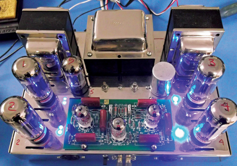
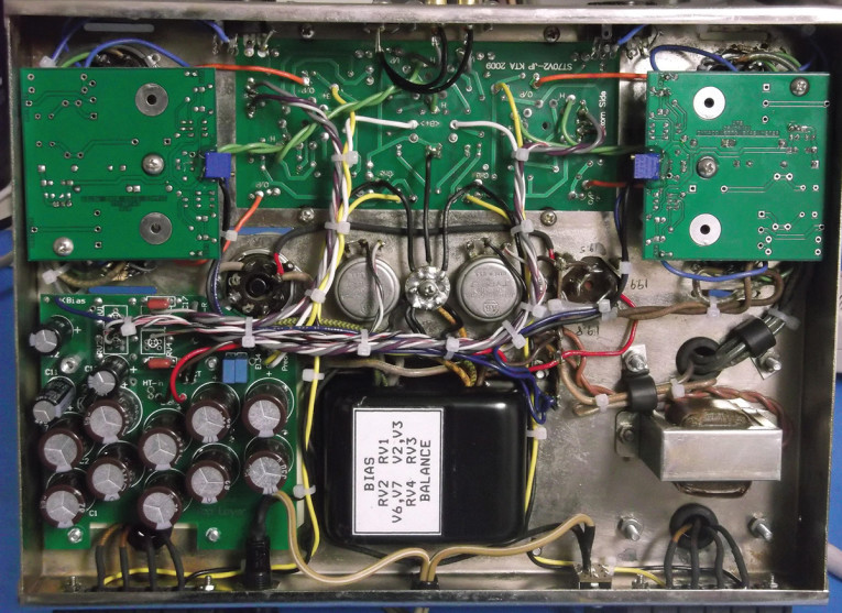
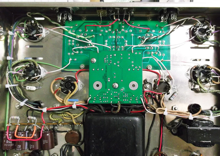
I thought this would look cool and tried such an installation on the second S70 I modified. I used the PCB’s original mounting hole plus the voltage regulator hole so the boards would be secure and would not rotate. I added balance potentiometers on the new driver board (by KTA) that are visible if you look closely (see Photo 10). I also added a new power supply PCB (Classic Valve Designs). I used the original chassis mounted bias potentiometers for bias level instead of the hard to access ones on the Classic Valve Designs’ power supply PCB. Photo 11 shows the trim potentiometers I added to the two comparator boards to make the bias set point reference voltage easily adjustable in order to try different current settings.
Sorry, no warranties expressed or implied. Best of luck to you and always ensure the filter capacitors are fully discharged before you begin. aX
E-mail the author
This article was originally published in audioXpress, April 2013.