- on Theory Articles
- Article
The Sweet Spot - Part 2
Push-Pull Operation
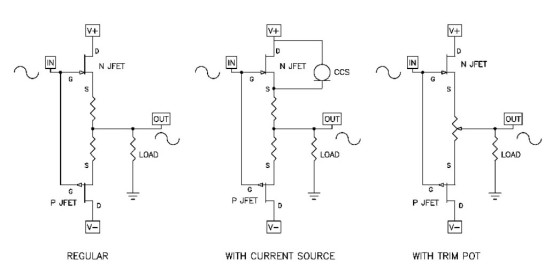
Of course, single-ended Class A is not the only way to operate gain devices. Large reductions in distortion can be had by operating gain devices in push-pull, where two similar devices operate in balanced opposition such that their second harmonic characteristic is naturally cancelled.
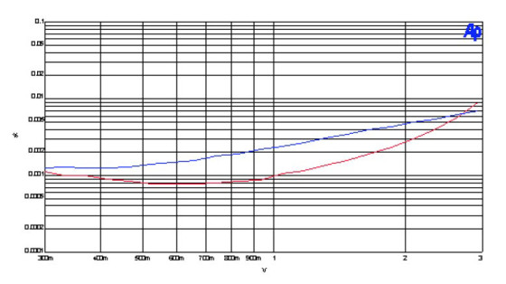
On the left in Fig. 18, you see a pair of JFET followers operated push-pull. So wheres the sweet spot for this sort of circuit? Its there if you go looking for it. The sets of curves in Figs. 19-21 show three techniques for getting a pair of these devices into the sweet spot. First, you can take the regular follower in Fig. 18 (left) and simply vary the supply voltages a bit. The curves in Fig. 19 show distortion for two examples, the upper curve being with two equal supply voltage values. The lower curve shows what can happen if you vary only one of the supply voltages.
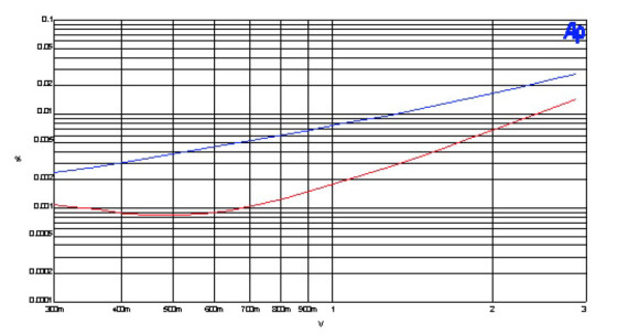
Figure 20 shows a technique we employ at Pass Labs the use of some single ended bias in a push-pull output stage to reduce distortion. The distortion curve shows what you can get if you simply put a small value current source in parallel with one of the JFETs as shown in the Fig. 18 (middle) circuit. The current source displaces the bias current values on the JFETs until they achieve a more perfect distortion cancellation.
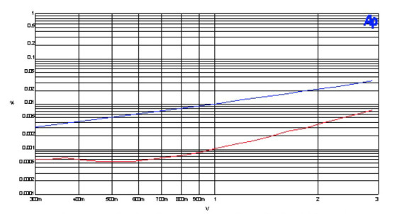
There is yet another way, shown by the circuit on the right in Fig. 18, which involves the use of a trim potentiometer instead of the Source resistors of the regular circuit. Figure 21 shows that a simple adjustment of the pot can drop the distortion by 90% without having significant effect on the other aspects of performance.
Temperature
There is one last important variable affecting performance and the location of the sweet spottemperature. All of these gain devices have transfer curves which are some function of the temperature of the device. All those transfer curves I have shown you will be different if you vary the temperature.
Conceivably you could adjust for the sweet spot by varying the temperature. More practically, you will want to see to it that your circuits have reached their ordinary operating temperature before adjusting for the last bit of performance.
Cascoding, Paralleling, And Transforming
So what do you do if its impractical to find the optimal load-line in a given circuit? Occasionally the sweet spot occurs at voltage values that are impractically low, or at currents that are higher than a device can handle for a given voltage.
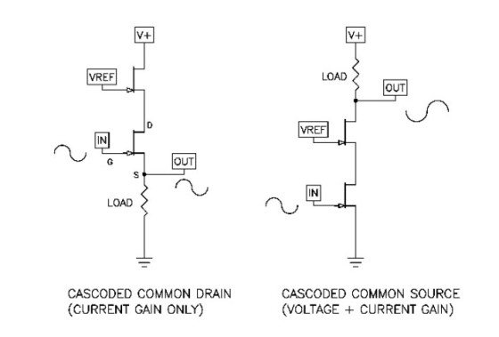
Here are three things that a designer can do to get into the zone: The first is cascoding, where the gain device is coupled with a Common-Gate/Common-Grid/Common-Base (depending on the type of device!) tube or transistor which adds practically no influence of its own but which allows a more arbitrary DC and AC voltage across the gain device. Figure 22 shows a couple of examples, using JFETs in both Common-Drain and Common-Source circuits.
The top JFET is the cascode device, and its Source voltage, which will be seen by the Drain of the JFET below it, is set by Vref. The idea is that the cascoding device provides a voltage umbrella for the gain JFET, and all manner of voltages can appear at the output of the circuit while the gain device sees all, a portion, or none of it.
Its pretty easy to get into the sweet spot using a cascode, and if you want to explore this in some more detail, I recommend Zen Variations #9, available at www.passlabs.com or aX 5/06, p. 6. This article explores getting the lowest possible distortion from an amplifier using a single stage with a power JFET having a high current rating, but a low voltage and dissipation rating.
Another way to get into the zone of the sweet spot is to parallel devices. There are times when the load is too low (and you cant change it) or the voltage is too high, but often you can mitigate this situation by operating devices in parallel. This way you can limit the dissipation of each device, and the load appears as a multiple of the number of devices.
The third method is to use a transformer, which allows you a flexible range of voltages and currents through the device while delivering the appropriate values to the load. Tube amplifiers do it all the time, and it gives the extra flexibility that then allows you to adjust for the sweet spot.
Theres A Small Catch
All the loads you have examined are resistors. Many times that is all you need to work with anyway, but when it comes to loudspeaker drivers and passive crossovers, you must contend with loads which are also reactive and which vary in impedance.
This can be a problem when the load-line that gives the best performance depends on resistance. A reactive load will take it out of the sweet spot. This is particularly true for tube amplifiers operating single-ended Class A without feedback much of the performance depends on triode load-line cancellation.
These amplifiers are particularly appreciative of resistive loads, and if you have this situation, its worth considering ways to flatten the load impedance, giving a more resistive load for the amplifier. There is another solution to this problem if you employ cascoding. Again, Zen Variations #9 includes a technique I have dubbed Cascode Modulation, in which the gain device can be made to see controlled load-line voltage variations which are only a function of the output current, and not related to the output voltage. In this way, the sweet spot is preserved into any load reactance or impedance, and it is very easily dialed in by adjusting a couple of resistor values. In the Zen example, you get a 90% improvement in distortion by simply attaching the cascodes voltage to a different spot, without changing any values or any other characteristics.
Conclusion
So there you have it. As an audiophile you want the best performance, and you probably arent above spending money and trying tweaks of various sorts to help you get it. But there are real improvements that can be had without extra accessories or emptying your wallet.
Amplifying circuitry can be made better without more complexity and without more feedback. The best part of this for do-it-yourselfers is that you can do this on your own bench, costing mostly just the time it takes to tweak the circuit and evaluate the results. Moreover, this approach is not seen on the factory floor for most manufacturers its simply too time consuming to do, and the rest probably never heard of it.
So heres your chance to make simple high-quality audio amplifiers better than ever. Buy yourself a cheap used distortion analyzer and go for it.
This article was originally published by audioXpress, January 2010.