Do you plan to work with transmission line speakers? Before you begin, consider the effects of stuffing on your transmission line speakers. In the April 2010 edition of audioXpress, Cornelius Morton examined the effects and described a test setup with mics in a cardboard tube, a preamp, scope, sweep/function generator, and mini receiver.
Morton wrote:
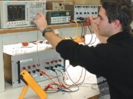
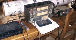
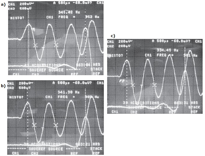
Note that Photo 1 shows the test setup with mics in cardboard tube, preamp, scope, sweep/function generator, and mini receiver. Photo 2a shows a reading without stuffing. Photo 2b is test run 2 with stuffing. Photo 2c is test run 3 with additional stuffing.For transmission line speakers, the effect on the velocity of sound of stuffing the line with fibrous material is of some import. However, information on this subject is sketchy at best and rife with myth, ranging from no effect at all to only an effect if the stuffing is packed nearly solid. Thus, the purpose of this article is to add some science to the discussion.
TEMPERATURE CHANGES
But first, a bit about air and the velocity of sound. Let P equal air pressure and p equal air density, then the velocity of sound, Vs, is equal to (k × P/p)0.5, where k is a function of temperature.
For constant temperature, if the pressure is reduced by 50%, then the density is reduced by 50% and P/p remains the same. Measuring the velocity of sound in a house in Denver at 72° F and taking the same measurement in a New Orleans home at 72°F results in identical readings. The reason that the velocity of sound varies with altitude is that free air temperature decreases as altitude is increased.
Air temperature determines the velocity of sound. As a rule of thumb, the velocity of sound changes by 60cm/s for a 1° C change in temperature. A more accurate calculation is Vs = 331.3 × (1 + Ta/273.15)½, where Ta is the air temperature in degrees C and 331.3 is the velocity of sound in meters per second at 0° C.
I used an 8″ OD × 48″ long cardboard concrete form to mount two microphones and as a container for the stuffing. I placed the mikes inside the form so that the distance between the diaphragms equaled 1m, or 39.37″, or 39 3/8″ on my ruler. The microphones feed the A and B channels of a Heathkit SP2 preamp. The A channel lead mike drives the A channel of a Tektronix 2430A digital oscilloscope (www.tek.com). The preamp B channel drives the B channel of the scope. A B&K 3020 Sweep/Function generator provides the test signal, a six cycle 1kHz tone burst that repeats several times a second. One channel of an Optimus STA-20 mini receiver receives the test burst and drives a small two-way speaker, the Optimus STS-50, for the sound source. A Centigrade thermometer reading ambient air temperature rounds out the test setup as shown in Photo 1.
For the initial settings, I adjusted the scope to synch on channel A, alternate channels, a 500 µs per cm time base, and set the cursors to read time between cursor one and two and display 1/time. Note that in this case the 1 represents 1m, so that 1/time equals velocity.
TESTING
Adjusting the sound level from the speaker and the channel gains for a convenient display results in the display readings of Photo 2a, reference readings without stuffing. I measured the sound velocity at 345.4m per second. The air temperature for this run was 24° C and the calculated Vs is 345.55m per second. This is an excellent correlation, 0.04%, and verifies the test setup.
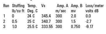
For the second test run, I stuffed the tube with one-half pound of fiber fill, a crimped polyester fiber sold at many craft stores. The stuffing ran from behind the A microphone diaphragm to the front of the B microphone windscreen, 36.5″, a volume of one cubic foot. The raw results are shown in Photo 2b. The temperature at this time was 25°C requiring that the test Vs of 341.3m per second be reduced by 60cm to 340.7m per second. I added an additional onehalf pound of stuffing and repeated the test. The raw results are shown in Photo 2c. The ambient temperature for this test was 25.5°C decreasing the raw Vs of 334.45m per second by 90cm to 333.55m per second (see Table 1).
The velocity variation is –1.36% for run 2 and –3.43% for run 3, effectively increasing the length of a quarter wave tunnel tuned to 50Hz, 1.727m in length, by 5.9cm or a bit over 2″ when stuffed to 1 lb per cubic foot. Does this mean that I can choose a stuffing density of 1 lb/ft3 and cut the tunnel length by 3.43%? Not quite; the velocity change is not the purpose of the stuffing—only a secondary effect—the real purpose is to lower the Q of the driver and the quarter wave tunnel/transmission line.
STUFFING THE LINE
A transmission line speaker is made up of two coupled mechanical resonances and an electromagnetic motor. The resonances are:
1. The free air resonance of the driver, consisting of the combined masses of the cone, voice coil, and air load, and the compliances of the surround and spider.
2. The resonance of the transmission line, which is determined by the line length and the velocity of sound within the line.
In the transmission line speaker both resonances are tuned to the same frequency, the line being tuned to the driver Fr. When the driver is energized in an unstuffed line, two impedance peaks are found, one below the tuned frequency and one above, which is typical for an overcoupled system of two resonators tuned to the same frequency. Overcoupling occurs when the coefficient of coupling, k, exceeds a critical value, kc = 1/(Qd × Qt)0.5, where Qd is the Q of the driver at Fr and Qt is the Q of the transmission line at resonance. Note that Q is a magnitude only and represents the same in electronics as mechanics; namely, the energy stored in a cycle versus the energy lost in a cycle.
When the coupling value exceeds kc, the double beaked response occurs with the peaks increasing in value as the coupling is increased. The null in the impedance curve of the driver at Fr is due to both the driver and the transmission line acting as resistances at the tuned frequency, the line absorbing most of the back wave energy from the driver and controlling cone excursions. Below resonance the driver impedance is mostly a compliance, while the coupled impedance from the line is inverted and thus resembles a mass.
At a few cycles below resonance the coupled mass cancels the driver compliance, resulting in the low frequency peak. Above resonance the driver impedance is mass while the coupled impedance resembles compliance. Again, at a few cycles above Fr, the impedances cancel, resulting in the high frequency peak. These two peaks are true resonances and therefore store and release energy, distorting the speaker sound. In the transmission line system the coupling is provided by the cone and is relatively large and fixed.
The Q of the driver is determined by the DC resistance of the voice coil, the frictional losses of the spider and surround, and the frictional losses of the air load including the transmission line. In free air the driver Q is typically limited to values between 3 and 5 when driven by a modern amplifier. The Q of the transmission line is determined by the line length, circumference, and roughness of the inner surface.
To lower the peaks in the response around resonance requires that either the coefficient of coupling be decreased, cutting holes in the cone(?), or increasing kc. Increasing kc may be accomplished by decreasing Qd or Qt. Stuffing the line does both, increasing the friction within the line and increasing the friction of the air load on the driver. Typically the line will be stuffed so that the peak to valley ratio of the two peaks and the null at Fr is not more than 2 to 3dB.
You might guess that the stuffing density will be between 0.5 and 1 lb/ft3 and cut the line 2.5% short. Will being a percent or two off hurt? Not much for a 50Hz Fr. If the line resonance is 49Hz, then the coupled resonance will be (50 + 49)/2 = 49.5 Hz, and the line will stuff normally. Readers with sharp eyes and ears may have noticed that the Rayleigh open end correction has not been mentioned; it is the effective lengthening of a circular pipe due to the transition from the pipe to the open air and at low frequencies the added length is equal to 0.62 × r (where r is the pipe radius). For rectangular pipes r is calculated from the mouth area A, r = (A/3.1415)0.5. Fortunately the stuffing within the transmission will provide a two-way loss that is great enough that the correction coefficient approaches zero and may be ignored.—C. Morton, “Stuffing and Sound Speed,” audioXpress, April 2010
Editor's note: This article originally appeared in audioXpress April 2010.