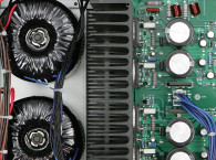
How Transformers Work: A Quick Review
Grossly oversimplified, a transformer works by converting an AC current to a varying magnetic field, and then back into an AC current. Coiling wire into a “winding” and passing current through it produces the magnetic field. Conversely, the field passing through another winding induces a current in it, which is used to drive the load.
In a power transformer, the “primary” winding is driven with AC line voltage — the power that comes out of the wall. The voltages required for the rest of the system are generated in “secondary” windings. All the windings are placed on a “core” made of an iron alloy. This is done because the permeability, or magnetic conductance, of iron is much higher than that of air, which allows a transformer to work much more efficiently.
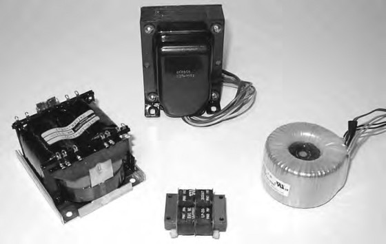
There are many different ways to build the core using different materials, processes, and shapes. I’ll describe a number of the more common types in detail (Photo 1) a little later.
Magnetically Induced Noise And Stray Flux
If you’ve built much audio equipment, chances are that at one time or another you’ve run into a problem with line-frequency noise getting into the audio signal signal path. Sometimes this problem is simply the result of not enough filtering or regulation of the DC power supply, or perhaps a ground loop in an input circuit.
But often, magnetic coupling from the AC power transformer is the culprit. In a perfect transformer, the entire magnetic field generated by the primary winding would be contained entirely within the transformer and pass through the secondary winding(s). Of course, nothing is perfect, and there is always at least some part of the magnetic field that escapes from the transformer.
This field, called “stray flux,” is a primary concern in the selection of a transformer for audio equipment. If an AC magnetic field that leaks from the power transformer intersects a wire (or PCB trace), it will induce a small current into that wire, just as if it were a secondary winding on the transformer. The resultant noise voltage produced is generally very small, but in audio equipment, even a few millivolts of noise in a sensitive circuit can be audible.
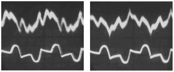
Photo 3 (right): Oscilloscope pattern showing output noise (top trace) and the current through the plate winding, using the horizontal EI-core transformer. Note the spikes from diode reverse recovery.
The noise waveform on an oscilloscope is usually not sinusoidal—instead, it looks more like the combined waveform of the current drawn from the secondary(s), which has a much sharper peak, resulting from the filter capacitors charging on the rising edge of the AC waveform. You can often see large spikes that correspond to the reverse recovery current in solid-state rectifiers, which is probably a subject worthy of an article itself.
Photos 2 and 3 show oscilloscope patterns of stray-flux noise in a tube headphone amplifier, which I’ll talk about more later. The easiest way to see whether you have a stray-flux problem is to move the transformer away from the rest of the circuitry. Since the strength of a magnetic field drops rapidly with increasing distance from its source, often moving the transformer only an inch or two will diminish the noise dramatically.
Sometimes — especially in power amplifiers — just keeping the transformer away from low-level circuits is an effective method of dealing with stray flux. But in other situations, as in a phono preamp, the design of the transformer itself needs to be addressed to provide acceptably low noise in the finished product.

the case removed.
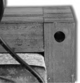
Photo 5: Close-up of the lamination gaps
in an EI-core transformer.
Core Type — The Many Different Ways To Build A Transformer
You can build low-frequency power transformers in many different shapes and configurations. I’ll discuss a number of them in detail, starting with the most commonly used types, describing their construction and their suitability for use in audio equipment.
Almost all power transformers share some common characteristics. Typically, they are wound on cores made from thin sections of an iron alloy, usually a type of steel made just for this application. Thin sections are used instead of a solid piece to prevent currents from being induced in the core itself—iron, after all, is an electrical conductor as well as a conductor of magnetic flux.
Different physical configurations and manufacturing methods for transformers have evolved over the years in an effort effort to design a better product. One goal is to design a transformer that is nearly 100 percent efficient—meaning that all the energy in the primary winding is coupled to the secondary, and is not wasted by heating up the core or windings, or leaking magnetic flux outside the core. Another goal is to design transformers that are inexpensive to manufacture. As you might expect, these two goals are generally at odds, and the better the transformer is, the more expensive it is to build.
The EI-Core Transformer
The most common type of AC power transformer is called an EI-core transformer, because the laminated iron core that it’s wound on — before assembly — looks just like the letters “E” and “I.” Photo 4 shows an EI-core transformer with the outer casing removed.
In an EI-core transformer, the windings are wound around the center leg of the “E”-shaped core piece, and the “I”-shaped part is joined to the “E” to form a closed magnetic path. In reality, the thin, stamped “E” and “I” laminations are stacked up in alternating directions and assembled with a form, or “bobbin,” containing the pre-made windings. The joint between the “E” and “I” is alternated between the two sides of the transformer to give the core greater mechanical strength.
While the EI transformer is the least expensive and most common type of transformer, it is also one of the worst in terms of its stray flux. The problem is all those “E” to “I” interfaces—there is always an air gap, no matter how tiny, between the laminations. Each of these gaps (there are three for each lamination), visible in the close-up (Photo 5), provides an opportunity for magnetic flux to leave the core.
Several “fixes” applied to EI transformers help lower the stray flux. The most common is to place a conductive “flux band” around the transformer. This band, usually made of a thin sheet of copper, is wound around the transformer in the same orientation as the windings, but completely outside the core. It is soldered together to form a continuous loop.
The flux band works by acting as a shorted turn around the outside of the transformer. Any flux lines that cut through the band induce an eddy current that produces an opposite magnetic field, which tends to cancel out the original flux. Another often-used fix is to weld an iron strap around the outside perimeter of the core. This tends to contain, rather than cancel, the stray flux, since the iron strap has a much higher permeability than the air around it. Similarly, the entire transformer can be contained, or potted, inside a ferrous metal can.

for a tube headphone amplifier.
The Toroidal Transformer
The toroidal transformer, or “toroid,” is a familiar sight inside high-end audio equipment. The toroid looks like a doughnut, with windings equally spaced around the diameter of the transformer (Photo 6). Toroids are also available potted inside metal or plastic cans, or molded inside plastic resin and equipped with pins to mount directly onto a PC board.
Like the EI-core transformer, the core of a toroidal transformer is made of an iron alloy, but instead of being composed of multiple, stacked laminations, it is wound from a single strip of metal, much like a roll of tape. The fact that there are no discontinuities in the core makes the toroid very efficient and reduces stray flux to around 10% of that of a comparable EI transformer.
Toroidal transformers still leak magnetic fields, mostly because the windings are not symmetrical — the wires are spaced farther apart on the outer diameter of the core than the inner. Generally, toroidal transformers are smaller (by up to 50%), quieter (magnetically and sonically), and more efficient (95% versus 80%) than comparable EI core transformers. If they are so much better, you might wonder, why doesn’t everybody use them? The answer, as you might guess, is because at power levels under 500W, they’re much more expensive. This cost premium is mostly because they are much more difficult to manufacture.
Since there is no “open end” on a toroidal core, you cannot wind the wire onto a bobbin and slide it onto the core, as is done for an EI transformer. For each turn of wire, the entire length of the winding must pass through the hole in the core, making the toroidal transformer much more difficult and time-consuming to wind.
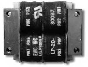
UI-core transformer.
The UI-Core Transformer
UI cores are similar to EI cores, without the middle leg of the “E.” Also like EI cores, UI cores are made of stacked laminations, so they suffer from the same gaps in the magnetic path that EI cores do. These discontinuities result in flux escaping from the gaps in the core.
UI-core transformers are sometimes made with the windings all on one leg of the core (a common construction for very high voltage transformers), but usually the primary and secondary windings are placed on separate bobbins on opposite sides of the core. This results in a “semi-toroidal” construction, with the windings oriented to help cancel out any stray magnetic fields.
The most common application of this type of core for power transformers in audio equipment is in small PCB-mount transformers (Photo 7). A small PCB-mount UI-core transformer is often a better choice than a conventional EI-core transformer for low-power audio equipment use. These inexpensive, compact types tend to radiate a little less magnetic interference than a comparable EI-core transformer. They still have much more stray flux than a toroidal transformer, so keep them a good distance from low-level circuits.
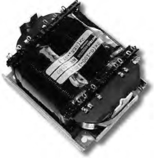
C-Core Transformers
C-core transformers are made on a core that is wound from a single strip of material, like a toroid. The core is wound with two straight sides, so it is shaped more like an oval than a circle. After the core is wound and impregnated with a glue to hold it together, it is cut into two pieces, each in the shape of the letter “C.” This allows assembly of the pre-made windings onto the core, which is then put back together.
C-core transformers can be made with a single core (one magnetic “loop”) or with two (often called a “double C-core transformer”). Like UI-core transformers, they can also be constructed with the windings wound all on one side, or on two opposite sides of the core.
As far as performance is concerned, you can consider C-core transformers in between toroidal transformers and EI-core transformers. Though they still have a break in the magnetic path, they have only two, which can be minimized with careful finishing of the core. The wound construction of the core also results in higher magnetic efficiency than a stacked core. When constructed with windings on opposite sides of the core, the symmetrical construction helps to cancel stray magnetic fields as well.
Although C-core audio transformers for tube amplifiers have had fairly wide acceptance (at least in Europe and Japan), C-core power transformers are not common in audio equipment. Photo 8 shows a medium-power C-core power transformer, a single-loop transformer with windings on both legs of the core.
R-Core Transformers
A more recent development is the “R” core, which you can think of as a cross between the C-core and a true toroidal core. R-cores are wound from a continuous strip of metal and are formed into a shape with two straight sides, like a C-core.
Instead of using a constant-width strip of metal, the R-core is wound from a strip of varying width, so that the finished core winds up with a circular cross section. Unlike the C-core, the R-core is not cut to assemble the windings — instead, the windings are done on a bobbin that is assembled over the circular cross section of the core, then rotated to wind on the wire.
The R-core transformer is nearly as good as the toroid in terms of stray flux. It has an advantage over the toroid because the turns of wire are spaced equally around the core, since they are wound on a straight section of the core.
The windings on a toroid are spaced closer on the inside of the core, and wider on the outside. The fact that the winding is done on a bobbin on a straight section of the core makes the R-core much easier to wind, lowering the cost of the finished transformer.
R-core transformers are currently used in mid- to high-end consumer electronics equipment from Japan. In the US, they are still quite uncommon and almost as expensive as toroids, but I hope this will change as they become more popular here. The R-core transformer has the potential to become the predominant choice for use in audio equipment, providing all of the benefits of toroidal transformers at a lower cost.
EI Versus Toroidal Transformers — A Case Study
I did some real-world comparisons of EI and toroidal transformers in the recent design of a tube headphone amplifier. I had custom EI-core and toroidal power transformers built for the amplifier, both with the same ratings. The transformers have two secondary windings — one 6.3V filament winding and one plate voltage winding.
I also considered an R-core transformer, but I could find only one or two vendors in the US who could produce such a transformer, and their prices and lead times were unacceptable. My first approach was to mount the EI transformer on the amplifier chassis in its “normal” vertical orientation, (Photo 9). As soon as the amplifier warmed up, it was apparent that there was a problem: a noticeable line-frequency buzz coming from both channels.
An oscilloscope trace of the noise waveform using the vertically mounted transformer is shown in Photo 2. The bottom waveform is the current in the transformer plate winding (measured with a small current transformer), and the upper trace is the noise observed at the amplifier output. Note the rough correlation between the two waveforms.
The noise waveform is quite complex — it is far from sinusoidal, and it does not resemble power-supply ripple. Moving the transformer away from the PCB made the noise disappear, so it was evident that there was a stray-flux problem. If I moved the transformer about 2″ away, the noise diminished to the point of inaudibility — and if I moved it closer to the input stage of the amplifier, the noise became much worse.
I found by experiment that if I placed the transformer in a horizontal orientation (Photo 10), the noise was much less noticeable. Apparently, the stray flux from an EI transformer radiates the most in the plane of the windings.
The output noise caused by the power transformer flux leakage was −54dBm.
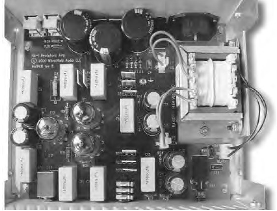
Leaving the transformer vertical and rotating it made little difference in the noise level. Photo 3 shows an oscilloscope pattern of the noise with the transformer mounted horizontally. The amplitude of the noise is slightly lower than it was with the transformer mounted vertically, and somewhat different in shape. Note the large spikes that correspond to the diode reverse recovery current—and the diodes used were soft-recovery diodes! It is interesting that these spikes were not so evident in the vertical orientation.
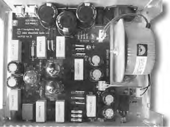
Because the noise level was still unacceptable, I experimented with all kinds of magnetic and electrostatic shielding around the transformer (including a flux band), but met with little success. No matter what I did, the EI transformer caused unacceptable levels of stray-flux induced noise into the low level section of the circuit. The only way I could reduce the noise level was to move the transformer, which wasn’t an option, since the enclosure was already designed and built.
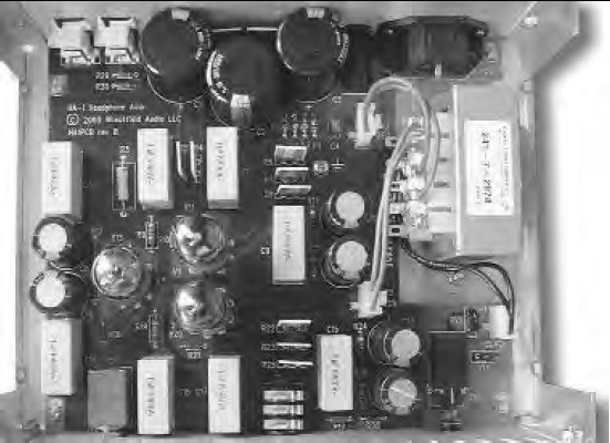
Though I preferred not to spend the money for a toroidal transformer in production, I was running out of ideas, so I turned my attention to the toroid. The transformer was mounted using a steel bracket into the same space as the EI transformer (Photo 11).
In the headphones, the difference between the transformers was immediately obvious. With the toroidal transformer, there was no noise to be heard. As shown in Photo 12, the remaining (inaudible) noise was composed of a combination of a small 60Hz component (interestingly, not 120Hz as you would expect from power-supply ripple) and the random noise generated by the components. Some radio-frequency noise was present as well, probably originating from a nearby AM broadcast transmitter. This noise was below the −60dBm level that I could meaningfully measure with my test equipment.

A comparison of the three transformer options is summarized in Table 1. The total cost of the three options shown include mounting brackets and hardware. Even though the toroidal transformer turned out to be twice as expensive as the EI transformer, it was the only acceptable solution for this application.
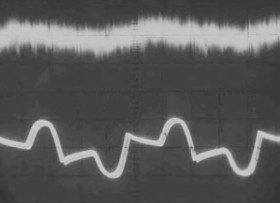
output noise (top trace) and the
current through the plate winding, using
the toroidal transformer. The noise
from the transformer stray flux is gone.
Conclusion
If you’re designing or building a piece of quality audio equipment, carefully consider your choice of power transformer. There are trade-offs to be made between the cost and performance of the transformer itself, as well as considerations in the rest of your design (such as where to locate the power transformer) that you need to think about.
Certainly, if cost is not the deciding factor, a toroidal transformer in audio equipment will provide superior performance in almost every respect when compared to a conventional EI-core transformer. But if you are careful with the location of the transformer, you can usually obtain adequate performance with EI transformers in all but the most noise-critical or space-constrained applications.
I hope more manufacturers (especially outside Asia) will invest in the production equipment to manufacture R-core transformers, and the cost of this superior technology will drop enough to make its use compelling. Other transformer technologies continue to be developed as well by leading consumer electronics companies, always striving to build better, smaller, and less expensive audio products. aX
Originally published in audioXpress, June 2001


