But, if you hadn’t noticed, the world isn’t perfect. The electricity that comes out of the wall isn’t always the same voltage. Components have tolerances and ratings, and sometimes the wrong combination of wall fluctuations, tolerances, and ratings makes components blow up or otherwise misbehave. You think I’m making this up? About five years ago I reviewed a combined soundcard and audio preamp-interface from a well-respected manufacturer. For the price, it sounded decent — until one very hot day. St. Louis in the summer gets pretty fierce, and all the air conditioners on the South Side were going full blast. That made the voltage at the plug sag, probably to about 108V AC, and the interface crapped out. Its raw DC voltage had dropped enough that the regulators were no longer regulating, and it hummed like a hive of bees.
It’s worth taking a little time to make sure this doesn’t happen, and between component tolerances and wall voltage fluctuations, it takes a fair amount of number crunching. That’s where a spreadsheet comes in handy.
The Thing Itself
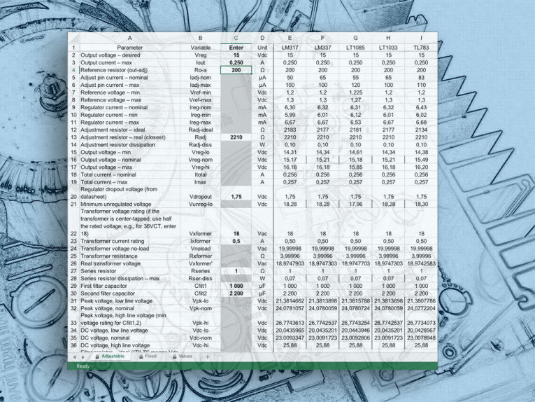
First things first: go to the Supplementary Material page on the audioXpress website (http://www.audioxpress.com/page/audioXpress-Supplementary-Material) - go to 2010 and 3/10 - and download the PowerSupply60Hz.xls or PowerSupply50Hz.xls files, depending on the line frequency in your country. The spreadsheets are in standard Excel format, and should work in just about any spreadsheet program; I’ve tried them in Excel, Quattro Pro, and the program in which they were actually written, OpenOffice Calc.
Each file has two main pages: one for use with common variable-output regulator chips, the other for fixed-output devices. But, everybody knows variable regulators are better, right? Well, I certainly prefer them for audio applications.
Actually, for serious audio work I like op amp-based regulators such as those designed by Jung(1) and Sulzer(2); I use variable-output regulator chips as pre-regulators for these circuits. Not everything is serious audio, though. For example, devoting extra board space, components, and money to a variable regulator seems like overkill if you’re building an LED level meter. So, after writing the page devoted to variable regulator chips, I made another one for fixed regulators, because you never know.
Circuits
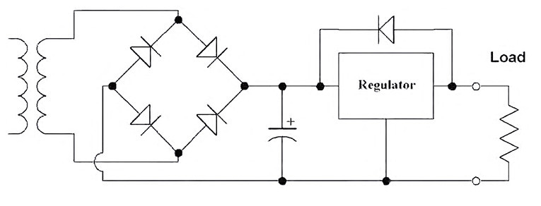
Figure 1 shows a typical slap-shot regulator. There’s a single big filter cap and a regulator, along with several glaring weaknesses:
1. There’s little provision for RFI proofing, either against line-borne crud or switching spikes from the diodes.
2. Because transformers are normally available only in certain fixed values (at least to small-quantity buyers), often you wind up dropping more voltage across the regulator than would otherwise be necessary. This makes it dissipate more power, so it needs a bigger heatsink.
3. Finally, this setup does an inefficient job of ripple reduction. Here’s an example: In a supply using an 18V transformer and drawing 250mA, a single 4,700μF filter capacitor yields 130mV of ripple. Using a two-stage filter with two 1,000μF caps and an 8Ω resistor, you get 103mV ripple, at about two-thirds the cost. (The trade-off, of course, is a bit more board space.)
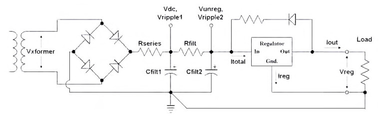
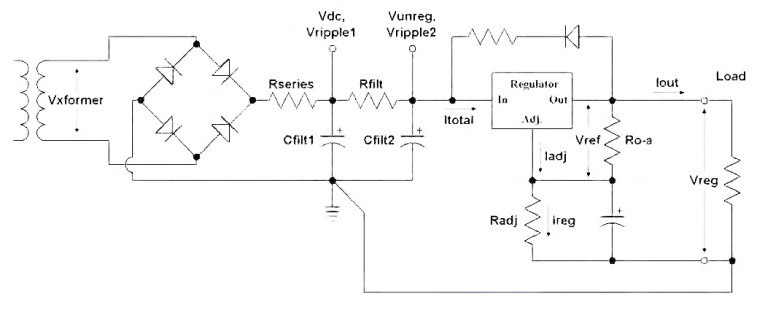
Figure 2 shows my preferred regulator design, using a fixed regulator; Figure 3 shows the same, but with a variable regulator. Regular readers of audioXpress will recognize this as a stripped-down version of the TriWay regulator(3). Note that, for simplicity, I’ve shown only a positive-polarity regulator and a single transformer hookup. For a negative supply, of course, you’d reverse the capacitor polarities and diode connections, and for a ± supply you might use a center-tapped transformer.
These circuit diagrams are stripped down to essentials. I’ve ignored some components — bypass caps for the outputs and the adjustable regulator’s adjust terminal, for example. Also, I’ve left out the possibilities of multiple parallel capacitors in the filter banks, although I do that on the TriWay board; for the spreadsheet’s purposes, only the total capacitance matters.
A word of warning: Many of the calculations in the spreadsheet are worst case scenarios. This means I’ve deliberately assumed whatever line voltage or parts tolerances will cause the most trouble. I’ll talk about that some more at the end of the article.
Follow The Bouncing Ball
I’ll go through the spreadsheet line by line, beginning with the fixed regulator sheet, because it’s simpler. First, a little geography; open the program and follow along with me.
The section to the left of the dividing line is where you enter numbers; your results will be on the right side. Actually, you can only enter numbers in the column marked ENTER, and only in some of the spaces; the rest are grayed-out and locked.
Scroll rightward to find the regulators that give you the voltage you want. (The left-hand columns stay put as you scroll.) For each voltage there are several regulators: two positive regulators and one or two negative. Why do I need separate columns for, say, the 7800 and LM340 regulators? Because their specs are a bit different.
Line 2 is the nominal regulated voltage. Let’s say you’re building a 5V positive supply to drive, perhaps, relays and logic. You’ll want to use either a 7805 or LM340-5 regulator. Line 3 is where you enter the maximum current you want to draw from the supply. For this example, enter 1A—note that the “Unit” column specifies amps, not milliamps. There’s logic built into the spreadsheet; if you enter more current than the chip can safely handle, the line will read “Too big” in the regulator’s column.
Line 4 is the nominal “quiescent current,” which is the amount of juice the regulator uses for itself; line 5 is the maximum. (Manufacturers don’t specify a minimum quiescent current.) As you can see, lines 4 and 5 are different for the 7805 and the LM340-5. Regulators have a nominal output voltage (it’s up in line 2), but they have tolerances. Line 6 is the lowest output voltage that’s within spec, and line 7 is the highest. Line 8 is the nominal total current—load current plus nominal quiescent current—while line 9 is the maximum total current, which happens when the quiescent current is at the high end of its tolerance.
For a regulator to regulate properly, there needs to be at least a minimum voltage between the input and output terminals. This is called the “dropout voltage,” and you can find the number on line 10. If you add the dropout voltage to the maximum possible output voltage (line 7), you get the minimum unregulated voltage, Vunreg, the regulator needs to see at its input terminal. That’s line 11 (I’ve added a fudge factor, which I’ll talk about later).
Line 12 is another place to enter a number: the specified AC voltage of the transformer’s secondary. There’s one complication; I’ve shown a single-ended supply, fed by a single transformer winding. If you’re using a center-tapped transformer with a bridge rectifier, as you might for a ± supply, you need to enter half its secondary voltage. A 36VCT transformer, for example, would be entered as 18V. For our example, try a 9V transformer rated at 2A; the current rating goes on line 13 (and if you put in a rating smaller than your maximum current draw, it’ll tell you “Too small” in the regulator’s column).
What the transformer actually does and what the specs say it does are two different things, and thereby hangs a tale.
Reality Series
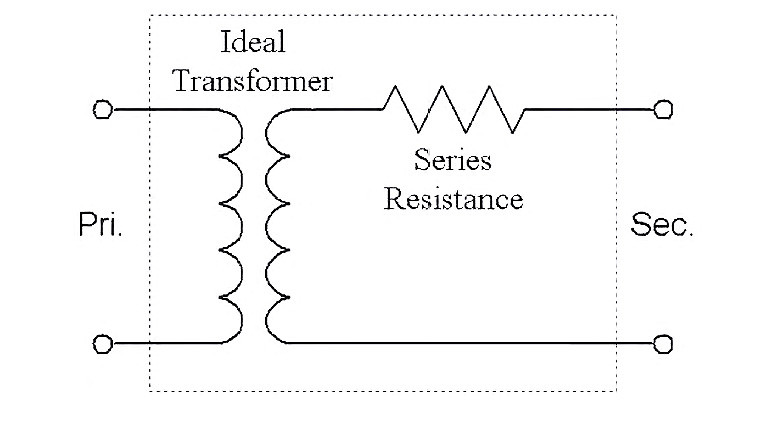
A transformer isn’t just a transformer — at least, not in the real world. You can model real transformers electrically as in Fig. 4, which shows a perfect transformer in series with a resistance. The (virtual) perfect transformer puts out the same voltage no matter how much current you draw from it, but in the real world, drawing current causes a voltage drop across the series resistance, so the real transformer’s Vsec drops when current is drawn.
Typically, the rated voltage of a transformer is not the “no-load” voltage, but the voltage it puts out when the rated current is drawn. The rated current, in turn, causes Vsec to drop 10% from its no-load value.
Line 14 computes the no-load voltage of the transformer. To do this, I’ve assumed that the manufacturer follows custom in rating the transformer as I just described. Line 15 tells you the equivalent resistance in the transformer, and line 16 indicates how much voltage the transformer is really putting out at the chosen current draw.
Figure 2 includes a series resistor between the diodes and the first filter capacitor. As I’ve mentioned in several previous articles, I’m a fan of Ben Duncan’s approach to power supply design (4). He believes in keeping lineborne high-frequency crud and diode switching noise as well isolated from the audio circuits as possible, and Rseries is part of that effort. In his designs, he typically bundles four 1Ω resistors in parallel; I usually use a single resistor, typically a carbon comp for low inductance.
Line 17 is where you enter its value — in this case, 1Ω. Because current passes through Rseries, it dissipates power. Line 18 tells you how much. Of course, because Rseries also exists in the real world, it has a tolerance. To compute its maximum power dissipation, I assume both maximum current draw (line 9) and a resistor 5% over its nominal value. Under these conditions, the spreadsheet calculates a maximum dissipation of 1.07W, so Rseries should be at least a 2W device.
Capacity And Necessity
Now come the two filter capacitors, Cfilt1 and Cfilt2; their values go in lines 19 and 20. This supply draws a highish current; let’s start with 2,200μF for each one. A rectified sine wave has a peak value. In theory, this ought to be the root mean-square (RMS) voltage times the square root of 2, but the diode bridges drop a bit in their P-N junction drops, and Rseries does, too.
Here’s where you begin factoring in the effects of changing line voltage. Line 21 shows the peak voltage at a bad time: the line voltage is down 10%, and Rseries is at the high end of its tolerance. Line 22 shows the peak voltage when everything is nominal, and line 23 shows the peak voltage when the line voltage is 10% high and Rseries is at the low end of its range.
The DC voltage produced by a supply with an RC filter is a bit lower than the peak voltage, and depends on multiple factors; I use a rule-of-thumb derived from the information provided on the HyperPhysics website(5). Line 24 computes the DC voltage across the first filter capacitor when the line voltage is low and the cap is at the low end of its tolerance — for most electrolytics, the tolerance is ±20%, which is a big range. Line 25 shows the DC voltage when everything is nominal, and line 26 shows the DC voltage when the line voltage is high and the capacitor is 20% bigger than its marked value.
Unlike previous calculations, this number is a function of the line frequency; a given capacitor is less effective at filtering out 100Hz ripple than 120Hz. That’s why I wrote separate spreadsheets for the two line frequencies. Line 27 shows the ideal resistor, Rfilt, for the two-stage ripple filter—but in this case, it reads “TILT!” What’s the problem? Line 24, the DC voltage when everything is low, is less than the minimum unregulated voltage calculated in line 11. Oops.
Assuming that you want to leave Rseries as is, there are two fixes to try. You could increase the transformer voltage, of course, but you’re already using a 9V AC transformer to get 5V DC. The other path is to increase the capacitance; let’s try 10,000μF instead of 2,200μF as Cfilt1.
That does the job; the TILT sign turns off, and a real value appears on line 27. It’s different in the 50Hz and 60Hz sheets. The resistor value in line 27 is the ideal, but there are a couple of constraints. One is the marketplace; some values are hard to find, particularly in higher wattages. The other is tolerance; if you chose a resistor rated at exactly the ideal value, it could be up to 5% higher than marked, which would drop too much DC in the filter. So instead, choose a resistor that is <0.95× the value in line 27, and then choose the next smaller commercial value. For convenience, I’ve made a third page to the spreadsheet, showing the E96 (1%), E24 (5%), and E12 (10%) resistor series.
For 60Hz systems, the next-smaller resistor than the ideal is 0.36Ω; for 50Hz, it’s 0.27Ω. Enter that in line 28. If you put in a resistor that’s too big, the sheet will tell you. Line 29 calculates the maximum dissipation for Rfilt, again under worst-case conditions.
Bottom Lines
The rest of the spreadsheet tells you how the supply will behave. Line 30 indicates the RMS ripple in the first filter stage. Line 31 tells you the RMS ripple in the second stage, at the regulator input, when everything is at its worst (capacitors 20% under nominal value, Rfilt 5% under). Oops, except line 31 says, “Too high.” What’s that about? I’ve mentioned a fudge factor in calculating the minimum voltage going into the regulator (Vunreg, line 11). That fudge factor is for ripple, and I’ve arbitrarily set it at 0.25V AC. If the ripple is higher than that, the sheet flags it.
How do you lower the ripple? You can’t raise Rfilt (that would drop too much DC), but you can increase the second filter capacitor, Cfilt2, to 10,000μF. In a 60Hz system, that works; ripple drops to 0.140V AC. At 50Hz, though, the ripple is still too high — remember that capacitors filter 100Hz ripple less effectively than 120Hz. At that point, you might try a cap that’s larger yet, but another possibility is to leave both capacitors at 10,000μF and raise the transformer voltage to 10V AC.
That changes a lot of numbers, including the ideal Rfilt. Instead of 0.27Ω, the proper value would be 1.5Ω, and the larger resistance means better filtering. Bingo—ripple at the regulator’s input drops to a very acceptable 0.048V AC. Of course, there’s no free lunch. In the 60Hz system, with a 9V AC transformer, Rfilt dissipates 0.39W, while in the 50Hz system with a 10V AC transformer, the increased voltage drop means more dissipation, to the tune of 1.61W. Engineering, as has been said many times, is the art of compromise; in this case, more heat (and a heftier resistor) for less ripple.
Line 32 is the nominal unregulated voltage; line 33 is the maximum unregulated voltage, worst case. From these numbers, the spreadsheet computes line 34, the regulator’s nominal dissipation, and line 35, the regulator’s dissipation under worst-case conditions. That tells you how much heat-sinking you’ll need on the regulator. (But see the Philosophical Detour, below.)
Oh, one more thing: the DC resistance in the transformer — as with any resistance — dissipates power as heat when current passes through it. Line 36 tells you how much.
Adjustable Regulators
The spreadsheets for adjustable regulator chips are quite similar to those for fixed regulators, although most of the
items are on different lines. The main differences come, as you’d expect, from the adjustable output voltages; these are controlled by a pair of resistors, which have their own tolerances, and by factors in the regulators themselves.
In producing these spreadsheets, I assume 1% metal films for the adjustment resistors. Using 5% resistors (or worse) leaves a lot more slop in the system, and requires more overdesign to keep the regulators regulating. Also, looser-tolerance resistors usually have poorer temperature coefficients, so the regulated voltages are more likely to drift. Besides, why bother? These days, 1% resistors are cheap.
Back To The Bouncing Ball
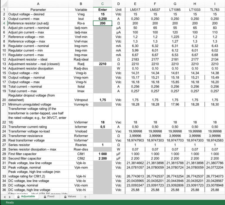
I’ll go over the adjustable-regulator sheet line by line, but since many of the lines mean the same thing as they do in the fixed-regulator sheet, I’ll save most of my explaining for the lines that are novel. I’ll use, as my example, a regulator designed to produce 15V at 0.25A, using LM317/337 chips.
Line 2 is where you enter the desired regulated voltage (15V); line 3 is the maximum current draw in amps (0.25A). On line 4, you enter the nominal value of the resistor between the output and adjust pins of the regulator, which I call Ro-a. Most of the time, I use a 200Ω resistor here (but refer to some discussion about this in the Tri-Way article3).
As with fixed regulators, adjustable regulators require a bit of quiescent current for “housekeeping.” It shows up at the adjust pin, so I call it Iadj. Like everything else, it varies from type to type and unit to unit; line 5 shows the nominal adjust pin current for each chip design, while line 6 shows the maximum.
Here’s how adjustable regulators work. The chip produces a reference voltage, Vref, between the output and adjust pins; it’s usually 1.25V nominal. (Lines 7 and 8 show the minimum and maximum values for Vref.) Since Ro-a is connected between those pins, the voltage dropping through Ro-a produces a current whose magnitude is Vref/Ro-a. Add this current to Iadj (typically much smaller), and you get the total regulator current, Ireg. (Lines 9, 10, and 11 show the nominal, minimum, and maximum regulator currents, respectively, taking into account variations in Vref, Ro-a, and Iadj.)
Ireg, in turn, passes through Radj, the resistor connecting the adjust pin to ground. In so doing, naturally, it produces a voltage, Ireg * Radj. That floats the regulator’s adjust terminal above ground. Because the output terminal is Vref higher than the adjust terminal, the regulated output voltage Vreg is Vadj + Vref.
All very well, but what should the value of Radj be? Line 12 computes the ideal value; you should select the closest value from the E96 series, and enter it on line 13. In this case, the ideal resistor is 2183Ω; the nearest E96 value is 2210Ω. Line 14 tells you that this resistor will dissipate, at worst, 0.10W, which a ¼W resistor can handle.
Variable Variables
The complication, of course, is that all of these numbers and values have tolerances. While, for example, Vref is nominally 1.25V on an LM317 regulator, it can actually vary from 1.2V to 1.3V. As mentioned before, the regulator’s housekeeping current can vary. And, of course, the resistors have that 1% tolerance. Put it all together, and you get a regulated voltage which varies. Lines 15, 16, and 17 show the minimum, nominal, and maximum regulated voltages, respectively. The minimum is about 14.3V (there are slight differences between the positive and negative regulators), the nominal voltage is about 15.2V, and the maximum is about 16.2V.
Lines 18 and 19 show the nominal and maximum output currents. Why are they at this place in the spreadsheet? Because, unlike fixed-voltage regulator chips, variable regulator chips have dropout voltages which vary significantly at different currents and temperatures.
That makes it impossible to include a fixed figure for dropout voltage. Instead, you’ll need to go to the regulators’ datasheets and get the dropout voltage from the chart presented there. After checking out these charts in the LM317-337 datasheets, assuming a temperature of 25° C, and doing a bit of interpolation, the dropout voltage at this current level will be about 1.75V, so that goes in line 20.
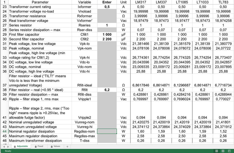
From here on, the spreadsheet for variable regulators is the same as the one for fixed. (I’m going to use the 60Hz sheet for my example.) For 18V AC 0.5A transformers (or one 36VCT transformer), Rseries = 1Ω, and both filter capacitors 1,000μF. I’ll wind up choosing Rfilt = 6.2Ω, which will dissipate 0.43W (so a 2W carbon comp would work). Ripple at the regulator input will be 0.206V AC, which is reasonably low, but using a 2,200μF cap for Cfilt2 reduces the ripple to <0.1V.
Nominal regulator dissipation (line 44) will be about 1.6W, maximum (line 45) about 2.6W. That tells you how much heatsinking to use on the regulator. Or does it?
Philosophical Detour
These dissipation figures are significantly different — the worst case is over 40% greater than the nominal — and they raise a philosophical question. How bad will things really be? How often will the line voltage and the resistor values and the capacitor values and the regulator’s output be at worst-case values at the same time?
Very rarely, in the real world. Electronic designers sometimes do “Monte Carlo” analyses, attempting to predict how often the tolerance dice will fall snake eyes. Assuming worst-case all the time leads you to over-designed systems, a real dollars-and-cents issue in the commercial world.
I plead guilty to doing this on occasion. Someone once said, joshing me, that if my supply designs were airplanes, they’d be too heavy to take off. Perhaps they’re right; in my own defense, though, my supplies never blow up or go out of regulation.
What’s a good compromise? A manufacturer would probably split the difference, using heatsinking appropriate to an intermediate figure between nominal and maximum. That’s why I included the nominal number. You can choose just how much fail-safe design you want. Another approach open to the home constructor is selecting components. If you buy several resistors and use a DVM to pick those that are very close to the ideal value, you take several variables out of the equations. Do that, and your most significant issues become chip voltage tolerances and (the big one) line voltage variations. With less variability, you need less over-voltage to avoid falling out of regulation — and that means less maximum dissipation and smaller heatsinks.
Playing Around
I’ve designed the spreadsheet to work with the most popular IC regulators, but the list isn’t exhaustive. You may choose to work with different ICs — or you may have different ideas about tolerances and such.
If so, go ahead and mess with the spreadsheet. For safety, I’ve locked all the cells except the ones for data entry, so you can’t accidentally overwrite formulas, but it’s easy enough to turn off the protection. The password is, logically enough, “protect.” Before you start playing, though, save a reference unmodified copy — and protect the sheets and documents again when you’re done!
Conclusion
A clean power supply is central to any good piece of audio equipment; if you think about it, the supply is in series with every audio circuit. My experience has been that, even with audio ICs that have good specs for power supply rejection, a well-designed supply can make a night-and-day difference to a project’s sound. I hope these spreadsheets can make their design quick and painless — and that your projects will sound better as a result. aX
References
1. Walter Jung, “Regulators for High-Performance Audio, Part 1,” Audio Amateur, March 1995, p. 8.
2. Michael Sulzer, “A High Quality Power Supply Regulator for Operational Amplifier Preamplifiers,” Audio Amateur, June 1980, p. 20.
3. Paul J. Stamler, “The Tri-Way Low Voltage Supply, Pt. 1 and 2,” audioXpress, January 2009, p. 8 and February ’09, p. 28.
4. Ben Duncan, “A State-of-the-Art Preamp: AMP 02,” Hi-Fi News and Record Review, November 1989, p. 45.
5. http://tinyurl.com/ripplecalc.
Circuit Boards
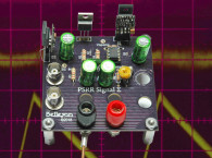
These spreadsheets will work for any low-voltage supply that uses IC regulators and a two-stage RC filter. They were explicitly designed, though, for the TriWay supply, a flexible three-output supply (two positive, one negative) which I discussed in the audioXpress articles cited (see References).
This article was published in audioXpress, March 2010.


