As the first power amplifier that broke $1 per watt barrier of listening power, the Heathkit W-7 was a major breakthrough for audiophiles. Introduced in 1958, it carried a list price of $54.95. The W-7 is not as common as the W-5, and when it comes up at online auctions from time to time, does not seem to attract the interest of many bidders. Their loss!
Features
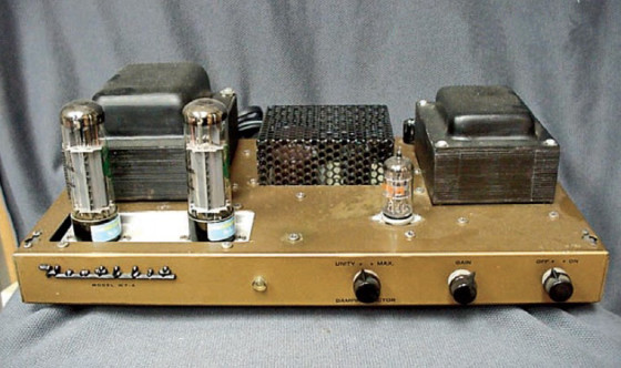
Each amp used two EL34s as output tubes, and a single 6AN8 tube as a preamp/phase inverter. The power supply used four silicon diodes in a voltage doubler. At 8½˝ deep by 6⅛˝ high by 15˝ wide, the unit was quite compact. Early models featured a satin gold enamel chassis with black wrinkle cages; later models had a black chassis and gold cages. The final models were designated “AA-91,” and production ended in the early 60s1.
Specifications were quite impressive. Frequency response was ±1.0dB from 6Hz to 30kHz at 0.25W, and ±0.5dB from 20Hz to 20kHz, at maximum rated output of 55W RMS2. Harmonic distortion was about 0.1% at 1W, rising to 0.5% at 20W and 1.5% at 55W. (A 2% total harmonic distortion is acceptable in music reproduction.) Hum and noise was 80dB below 55W. The amp utilized 25.5dB of negative feedback and featured 4.8-16Ω outputs as well as 70.7V line output. It also featured a variable damping factor switch on the front panel, enabling the selection of either maximum (20) or unity (one)2.
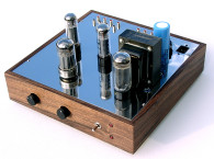
The output transformer in this unit is huge, much larger than the Mark 3 Dynaco amp that used 6550s, and is probably the reason this amp sounds so clean.
Operation
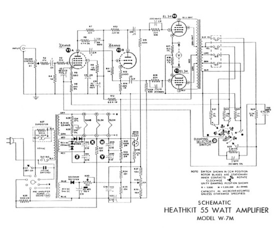
The circuit of the W-7 is simple and straightforward (Fig. 1). The signal is fed through a gain control and 0.1μF coupling capacitor to the control grid of the 6AN8. The amplified signal is coupled through an RC network to the grid of the triode section of the 6AN8, which is used as a split-load phase inverter.
The signal at the cathode of this stage follows the grid, while the plate voltage swings in the opposite direction. No amplification occurs at this stage. The two out-of-phase signals are coupled through 0.25μF coupling capacitors to the control grids of the EL34s. The output stage is operated in Class AB1; the screen grids of the output tubes are connected to taps on the primary of the specially designed output transformer.
A unique and elaborate bias supply and balancing circuit is incorporated in the W-72. This ensures accurate balance of the output tube’s plate current. Control R30 adjusts the bias voltage and is set to yield about –38V on the control grids of the EL34s, while control R38 allows you to balance the current between the tubes. This lets you use less than perfectly matched output tubes.
The high voltage power is supplied by a voltage doubler from the 180V AC tap of the power transformer. The 150μF and 200μF electrolytic capacitors are each rated at 300V, and in series would be equivalent to 75μF at 600V, and 100μF at 600V. This is a nice safety margin, because the power supply is designed
to 495V.
As I have mentioned in other articles, this philosophy was much different than that of Dynaco. In most Dynaco power amps, if the voltage used was 500V, then the capacitors were rated at 525V, and multicap cans were used to further cut costs and save chassis space.
Another unique feature of this amp is a sophisticated damping control. Heath’s explanation of the utility of this control is interesting: “Damping factor is defined as the ratio of load resistance to the internal resistance of the amplifier… It has been found that speaker systems which have a high degree of acoustical damping may be over damped when used with an amplifier having a high damping factor, with a resulting loss of bass efficiency.
On the other hand, too low a damping factor will result in boomy or one note bass which is undesirable”2. Speaker systems of this era were often efficient ported systems, or horns, but newer “acoustical suspension” systems were starting to appear on the market. This may be the reason variable damping was provided.
Dynaco equipment provided an economical entry into high fidelity. But when comparing the Dynaco Mark IIIs or IVs to the Heathkit W-7s, you will find that the Heathkit betters the Dynaco hands down. While the sound is somewhat similar, the Heathkit has more bass “kick,” and the treble sounds cleaner.
Another difference involves the transformers: Dynaco power transformers run quite warm, and after several hours of use are uncomfortable to touch. The Heathkits run cool, and after several hours are only warm to the touch. Sideby-side comparison of the Dynaco and the Heathkit shows where the “big iron” is; while the power transformers are similar in size, the output transformer of the Heathkit is half again the size of the Dynaco’s. While there is nothing wrong with the Dynaco transformers (I have many stock and custom amps that use them), I would rather get my hands on a W-7 output than Dynaco!
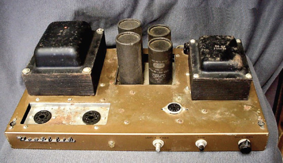
capacitor replacements.
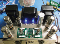
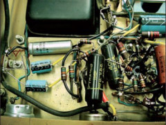
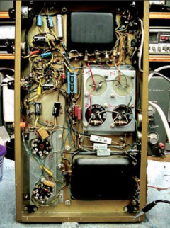
The unit as I received it is shown in Photo 2. As with my other rebuilds, I usually start with the power supply. In this unit, all the diodes in the voltage doubler were fine, but the electrolytic capacitors were leaky. I was able to find some 100μF 450V caps to replace the 100μF 300V versions in the first section.
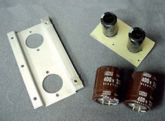
The original caps were about 1½˝ in diameter and about 4˝ tall. The new ones are about one-tenth this size (Photo 3). I removed the originals and mounted a piece of fiberglass board in the cutout and glued the new snap-mount ones to this board.
I was also fortunate to find four 330μF 350V electrolytic caps to replace the 200μF 300V originals. These were short, but sized to fit through the original chassis holes, and I mounted them using some chassis mounts (Photo 3).
Also shown in this photo is the original EL34 mount plate, which was extremely rusty. I wire-brushed and painted it. Note in Photo 1 the vented cages my friend Larry built for me to cover the new power supply capacitors. (Though these cages were not necessary for operation, he believes they give the amps
a finished look.) I replaced the selenium diode in the bias supply with a silicon diode, and also replaced the electrolytic capacitors in the bias supply, using 100μF 160V units for all (Photo 4).
I replaced the remaining electrolytic caps feeding the phase inverter and preamp sections. I then powered up the first amp with the Variac, and did some voltage measurements. Everything was in spec except voltage to the input grid of one of the EL34s. This type of problem is usually due to a leaky coupling cap, as was true in this case. I powered down the amp, and after waiting for the power supply to discharge, replaced all the coupling caps with new polypropylene. (My previous articles have covered capacitors and my thoughts on them, so I will not repeat here except to say I do not believe in spending huge amounts of money on “premium” caps. Use what you like.)
While you are under the chassis, use your ohmmeter to measure the value of all the resistor values. You will generally find several that have drifted off value, and this will affect the operation of your finished product. The 100K (R15 and R10) resistors that feed the EL34s should be very closely matched. Also carefully check the cathode resistors on the preamp section of the 6AN8 (Photo 5).
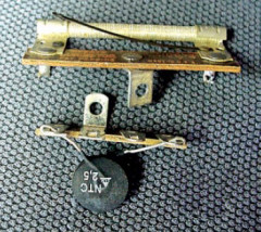
These amps use a “surgister” as a surge suppressor. Located in the corner of the chassis near the fuse holder, it is about 1½˝ long and looks like a small tube with wire wrapped around it. On the back side of the tube is a bimetallic strip, which closes the contacts as the wire heats up, acting essentially as a 100Ω
nichrome resistor that generates heat and closes the contacts, bypassing itself (Photo 6). I replaced this with a surge suppressor (sold for 50 cents by Electronic Goldmine), which works well for suppressing the turn-on surge of a tube amp with silicon rectifiers and cold filaments.
One of the interesting things I found with my pair of amps was that one was completely hand-wired as outlined in the manual copy I had purchased. The other amp had a factory-wrapped wiring harness. I have not been able to find additional information on this, but it was a very professional-looking harness, much like those seen in vintage military radios.
I contacted the manual copy source and asked whether they had any information on a W-7 manual with a factory-made wiring harness, but they had not seen any other W-7 manuals. This may also be a factory-wired unit.
The tubes used in this amp are very common and readily available. NOS 6AN8s are quite reasonable. The choice of available EL34s provides some outstanding representatives. I often use Svetlana EL34s, finding them very durable, and producing a nice clean crisp sound.
One of the nice things about the W-7 is that it does not need a matched set of output tubes, because the balance adjustment allows you to balance the current to the output tubes (so you can even use vintage unmatched tubes). The manual directs you to rotate the balance control to mid position and connect a voltmeter to the meter jacks on the back of the amp (the bias control should be fully counterclockwise and no inputs or speakers should be connected at this time), then turn on the amp and allow it to warm up for several minutes. You can see the two adjustment controls in Photo 7.
Adjust the balance control to get a zero reading on the voltmeter, continue to adjust to the lowest range of your meter, and readjust until it is zero. Once this is done, remove one of the leads of your voltmeter and connect it to the bottom terminal below the 70V output on the speaker strip. Adjust the meter for a reading of 0.36V, measuring across the 6Ω cathode resistor. This corresponds to 60mA current per tube (switch the lead between the meter jacks and observe the voltage on each tube).
I dug around in my used tube supply and found some Mullards, Tung Sols, and new Sovteks to try, and was fascinated by comparing the sound differences between the new and old tubes. I liked the Tung Sols the best, followed by the Svetlana, then the Mullards, and finally the Sovteks. (Not very scientific, just personal preference.)
These amps will drive just about any reasonable speaker system, they run very cool, and are not the least bit fatiguing. Very easy listening!
An additional skill I developed in this rebuild was replication of cosmetics, including logos and cabinet feet. These items are unique, and replacements are extremely hard to find. With materials available today, it is easy and fun to reproduce your own parts, giving your restoration an authentic appearance.

References
1. Vacuum Tube Valley, Issue 2, Volume 1, Fall 1995.
2. Heathkit Model W-7M Assembly Operation Manual, W7FG Vintage Manuals,
www.w7fg.com, 918-333-3754.
3. Schematic.
Parts List for W-7 Rebuiold, Per Unit
2 100-200μF 450V electrolytic (C13-14)
2 300-400μF 400V (or better) electrolytic (C17-18)
3 100μF 150V electrolytic (C15, C18, C19)
1 1N4005 silicon diode (replaces selenium)
1 25μF 50V electrolytic (C2)
1 25μF 450V electrolytic (C6)
1 0.1μF 400V coupling cap (C1)
1 0.25-0.27μF 600V electrolytic (C7-8)
1 surge suppressor, 2A minimum (replaces R27 surgister)
This article was originally published in audioXpress, May 2007.