Inspired by a presentation by Bill Whitlock, President of Jensen Transformers - a three-hour tutorial seminar titled “Audio System Grounding and Shielding: An Overview” - during the Audio Engineering Society convention in New York, Gary Galo decided to investigate a little more into the subject and do some reviews of the mentioned equipment.
On October 7, 2005, at the Jacob Javits Convention Center in New York City, Bill Whitlock, President of Jensen Transformers, Inc., gave a three-hour tutorial seminar titled Audio System Grounding and Shielding: An Overview. (Whitlock became President of Jensen following the untimely death of company founder Deane Jensen in 1989.)
Whitlock sought to dispel many of the myths surrounding grounding and system interfacing, noting that the subject abounds in black art and myths. Basic rules of physics are routinely ignored, and even many manufacturers “don’t know ground loops from Froot Loops” (the last comment was typical of the touches of humor that Whitlock brought to his presentation, though there was serious intent behind each of them).
If a system contains two or more pieces of grounded equipment, a ground loop may be formed if the chassis of the connected equipment are at different potentials. This will typically happen if the various pieces of equipment are powered by different AC branch circuits.
The most common approach to solving hum problems due to ground loops is by lifting safety grounds with “ground lifters” sold in any hardware store. Whitlock warned against this approach, noting that safety grounding keeps AC line voltages between equipment safe even if equipment fails. His view is that you should never use ground lifters even if a manufacturer’s instructions tell you that it’s OK to do so.
Whitlock noted that the ground adapters sold in hardware stores, while superficially appearing as ground lifters, are actually intended to provide a safety ground when grounded (3-pin) power cords are used with 2-prong receptacles. They are designed to add a ground, not remove one, by putting the outlet plate screw through the ground tab on the adapter! If ungrounded equipment suffers an internal failure of insulation or components at the AC line input, the equipment chassis can turn live with 120V AC if the safety ground is not connected (Fig. 1; I thank Bill Whitlock for granting permission to use slides from his Power Point presentation for these illustrations).
Whitlock also recommends GFCI (Ground Fault Circuit Interrupter) outlets for safety. These outlets sense differences between line current and neutral current (fault currents). Any difference between line and neutral current may be current flowing through a human, which can be a deadly problem. GFCI outlets trip at 4 to 7mA of current, protecting the individual in contact with the “live” equipment.
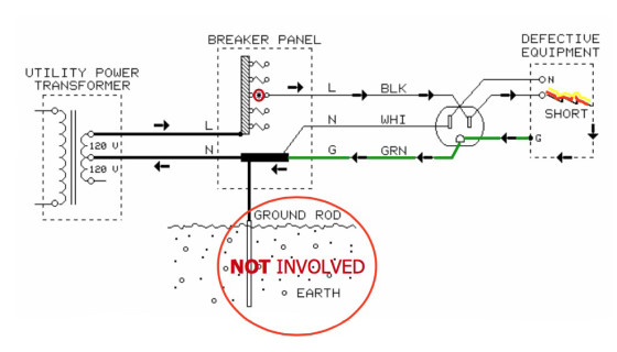
He also dispelled some of the myths surrounding earth grounds, noting that earth grounds are for lightning protection. The safety ground in a modern electrical system is tied to neutral at the entrance panel, and earth ground plays no role in protecting people from electrocution. Earth grounds are invariably not at 0V, and two earth grounds will rarely be at the same potential. Earth ground rods are useless for protection against fault currents, and are equally useless for reducing noise.
Hum Causes
Myths abound regarding the causes of hum in audio systems, and hum is rarely caused by bad audio cable shielding or AC distribution. You can trace the vast majority of hum problems to faulty system interfacing. Pro sound engineers routinely engage in dangerous practices in the field—adding ground lifters to AC power cords—in order to quickly eliminate hum problems. Defeating safety grounds is dangerous and illegal, and makes the person who did it legally liable.
Whitlock emphasized that such practices have resulted in people being killed and companies forced out of business because of lawsuits. The only safe way to solve hum problems is through proper system interfacing.
input transformers, noise coupling is effectively eliminated.
Whitlock provided a great deal of useful background on the causes of hum in unbalanced interfaces, and gave an excellent overview of the requirements for balanced interfaces. Balanced lines are not balanced because they carry audio signals of equal level but opposite polarity (though they normally do). They are balanced because of careful impedance matching of the two signal carriers with respect to ground, especially the source (driving) impedances. If the impedances of balanced lines are not carefully matched, by definition they are not truly balanced. Common-mode rejection will be compromised, which reduces the system’s ability to reject noise coupled to the signal carriers.
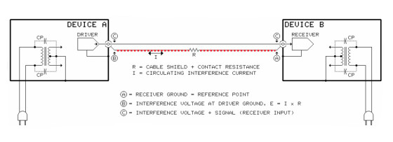
In unbalanced interfaces, leakage currents flowing in signal cables are the root cause of most hum problems (Fig. 2). Leakage currents are normally carried by the grounded conductor — the shield — which does not have a zero ohm impedance. Ohm’s law tells us that the resistance of the shield generates noise voltage over the length of the cable. This noise, in turn, is added to the signal at the receiver.
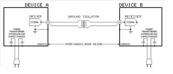
The correct way to eliminate hum problems in audio interfacing is with transformer isolation (Fig. 3). Transformers transfer the signal voltage from the primary to the secondary windings without any electrical connection between them. So, there are no noise currents flowing between the connected devices. With a properly designed transformer, hum is eliminated while safety grounds remain intact.
Reducing ground noise in a transformer-coupled interface depends on the type of transformer used. Output transformers typically have closely spaced primary and secondary windings. This increases the capacitance between the windings allowing efficient high-frequency noise coupling between the windings, which is undesirable. Input transformers typically employ a Faraday shield between the windings, which virtually eliminates capacitive coupling. This, in turn, greatly improves noise rejection of a transformer-coupled interface, including RF and ultrasonic interference.
Many transformer-based “black boxes” sold to eliminate noise caused by ground loop problems employ output transformers. Their low output Z allows these devices to be placed anywhere in the signal path, because their outputs are not sensitive to the capacitive loading caused by long cable runs. Input transformers, on the other hand, offer a 30dB improvement in noise rejection over output types. But, their relatively high output Z requires that they be placed within 2 or 3´ of the receiver in order to prevent degradation of their high-frequency response by the output cabling.
Whitlock noted that normally an unbalanced interface using a single isolation transformer close to the load will solve the noise problem. Only in unusual circumstances is a balanced interface necessary. Converting the entire interface to balanced is necessarily more complicated because it requires an unbalanced to balanced conversion at the source, and a balanced to unbalanced conversion at the load. In other words, two transformers rather than one.
One pet peeve of mine is the notion that professional audio systems should be designed to operate at matched impedances of 600Ω. Naturally, I was delighted when Whitlock dispelled this nonsense. He correctly noted that 600Ω impedances are holdovers from early telephone practice, but are not applicable to modern audio systems that are driven by signal voltage.
Modern audio circuitry is designed with low output impedances and high input impedances. This way, audio circuits are not subject to unnecessarily low Z loads. He also correctly noted that signal level, impedance, and line balance are three independent parameters. Impedance has nothing to do with level, and only its matching in the two signal conductors has anything to do with whether the line is balanced or unbalanced.
InGenius is a registered trademark of THAT Corporation.
Ingenius ICs
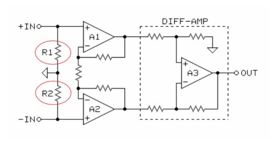
The near-infinite common-mode input impedance of a transformer-coupled line receiver gives it a huge noise-rejection advantage in real-world systems, but transformers have fallen out of favor in some pro audio circles. Transformer-less, actively-balanced circuitry has become increasingly popular over the past 20 years. Figure 4 shows a typical op-amp based, instrumentation-type of active differential input. This type of circuit has a disadvantage over transformers because the bias return resistors for A1 and A2 also lower the common-mode input impedance. You could raise the values of R1 and R2, but this would compromise the noise performance.
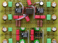
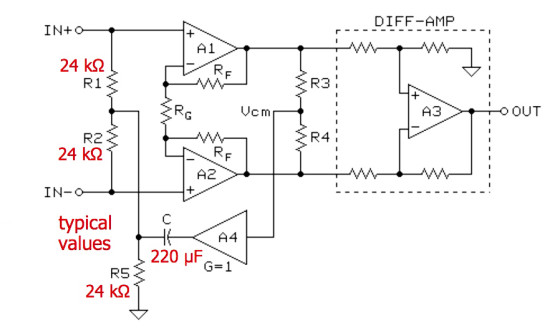
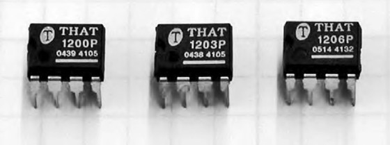
Bill Whitlock has designed an elegant solution to this problem (Fig. 5). The common-mode voltage is extracted at the junction of R3 and R4. A4 buffers the common-mode voltage and bootstraps R1 and R2 via capacitor C. This patented technique is being used in the InGenius line integrated circuit differential line receivers manufactured by THAT Corporation (Photo 1).
Common-mode input impedance for this circuit is 10MΩ at 60Hz and 3.2MΩ at 20kHz, without the noise penalty that raising the resistor values would produce.
Whitlock noted a number of features of the InGenius chips:
• Thin-film silicon-chromium resistors are used, which yield better stability over time and temperature compared to nickel-chromium or tantalum-nitride types.
• 90dB common-mode rejection ratio and gain accuracy are achieved by careful resistor matching, typically 0.005%. Laser trimming is used in the manufacturing, which keeps cost reasonable.
• Chips are manufactured using a 40V complementary bipolar Dielectric Isolation (DI) process, which allows NPN and PNP transistors with performance as good as discrete circuits. Isolation between transistors is high, with no substrate connection. Stray capacitances are low, yielding high bandwidth and slew rates.
• Front ends use a folded-cascode, PNP design, yielding superior noise performance, high gain with simple stability compensation, and greater input voltage range.
Whitlock also highlighted key performance specifications for the InGenius chips:
• High CMRR maintained with real-world sources:
• 90dB at 60Hz, 85dB at 20kHz with zero imbalance source
• 90dB at 60Hz, 85dB at 20kHz with IEC ±10Ω imbalances
• 70dB at 60Hz, 65dB at 20kHz with 600Ω unbalanced source!
• THD 0.0005% typical at 1kHz and +10dBu input
• Slew rate 12V/μs typical with 2kΩ + 300pF load
• Small signal bandwidth 27MHz typical
• Gain error ±0.05dB maximum
• Maximum output +21.5dBu typical with ±15V rails
• Output short-circuit current ±25mA typical
• 0dB, -3dB, -6dB gain versions = THAT 1200, 1203, 1206
He also summarized the performance advantages:
• Conventional active receivers are far cheaper, smaller, and lighter than a quality transformer, but
• Transformers consistently outperform them for reasons that need to be widely understood and appreciated.
• The main transformer advantage stems from its inherently very high common mode impedances.
• The InGenius IC exhibits the very high CM impedances previously associated only with transformers.
• Excellent noise rejection even with unbalanced sources!
• Its bootstrap feature lends itself to novel and very effective RF interference suppression.
• Its high-quality internal op amps give it great sound.
Whitlock highlighted his seminar with a lengthy Power Point presentation of over 150 slides, which we have made available here.
Available to download is also Whitlock’s 40-page seminar handout “Understanding, Finding and Eliminating Ground Loops in Audio and Video Systems”. Download it here.
The preceding highlights only scratch the surface of his presentation, so these documents are required reading for anyone interested in this subject.
Iso-Max Products
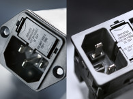
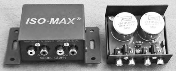
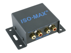
Jensen manufactures a multitude of transformers for every possible application, including microphone pre-amplification, moving coil phono cartridges, as well as balanced and unbalanced line-level usage. They also make a variety of transformer-based devices for audio interfacing. Perhaps the most useful for consumer applications is the CI-2RR Dual Ground Audio Isolator (Photo 2).
This stereo device consists of a pair of their JT-11P-1HPC Line Input Transformers.
Install the CI-2RR close to the load. In an audio/video application, a stereo RCA cable would be run from the video system’s main audio output to the CI-2RR. The output of the CI-2RR is then fed to the preamp, integrated amplifier, or AV amplifier line input. Jensen notes that to avoid excessive high-frequency losses, the output cable lengths should be no more than 3´.
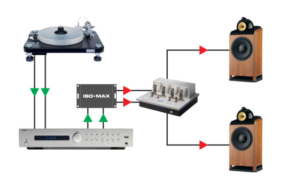
There may be cases where it is desirable to connect an audio/video system for both record and playback (Fig. 6). One possible application might be to use the audio recording capability of a Digital Video Recorder, DVD recorder, or VHS Hi-Fi recorder to capture an FM broadcast for delayed listening. For this application, use a pair of CI-2RR isolators, one in the record signal path, and one for playback. To keep output cabling as short as possible, place the CI-2RR used for the record signal path close to the video system’s audio record inputs. Place the playback isolator close to the audio pre-amp, amplifier, or A/V receiver.
In his review of the ISO-Max (audioXpress October 2006), Chuck Hansen notes the high frequency phase shift of the CI-2RR — about 35° at 20kHz — appears to be considerably higher than specified by Jensen. I made this measurement myself and got the same results. The graph in Jensen’s datasheets for the CI-2RR and the JT-11P-1HPC shows essentially 0° deviation from linear phase at 20kHz.
It seems strange to me that Jensen would use the same graph for the transformer and the CI-2RR, because the CI-2RR has a series R/C damping network at its output, consisting of 13k in series with 680pF. The R/C network should introduce phase shift of its own, beyond that of the transformer. I disconnected the R/C network in one channel of one of the CI-2RR devices supplied by Jensen. This reduced the phase shift to around 10° at 20kHz.
The datasheet for the JT-11P-1HPC shows a schematic of a typical application for this transformer, with a series R/C network of 13k and 620pF (the capacitor is a slightly different value than the 680pF used in the CI-2RR). You would assume that the phase graph on this datasheet would be for the transformer as a standalone device, and not with the series R/C network, but Jensen doesn’t really specify. None of the test circuits on page 2 of the datasheet show the series R/C network.
However, conventional phase measurements may not tell the whole story. Whitlock offered the following comments on the phase measurement: “Regarding phase measurements on the Jensen samples, let me emphasize that ‘phase shift’ is not necessarily phase distortion! A totally benign time delay is represented in the phase domain as a phase shift that increases linearly with frequency… this is not distortion. Phase distortion occurs when there is a nonlinear relationship between frequency and phase — in other words, a time delay that changes with frequency. The widespread confusion about this subject is why Deane Jensen published a 1986 AES paper, High-Frequency Phase Specifications — Useful or Misleading, and why Jensen always specifies Deviation from Linear Phase, or DLP, for our parts - not phase shift!”
“DLP is the true measure of phase distortion. The secondary R-C networks specified for Jensen input transformers are chosen to provide two-pole Bessel high-frequency rolloff, which guarantees minimal DLP as evidenced by zero-overshoot and zero-ringing in square-wave response. This time domain behavior is the hallmark of Jensen designs and a very important contributor to the sonic transparency of our products.”
You can purchase the AES paper mentioned by Whitlock as a PDF download from the AES website.
Enter 2398 in the box labeled “Preprint/Paper Number.” Cost is $5 for AES members and $20 for non-members. This paper is well worth reading.
Jensen uses standard PC-mount RCA jacks for the CI-2RR. The parts in the output R/C network appear to be Panasonic P-series polypropylene capacitors and 1% metal film resistors that look like the Yageo types sold by Digi-Key.
Subjective Tests
I evaluated the CI-2RR by inserting it in the signal path between my outboard D/A converter and my preamplifier. I use D.H. Labs’ Air Matrix cables fitted with their Ultimate RCA Connector for all of my system interconnects, so I used an additional 1/2-meter pair of these cables to connect the CI-2RR to my preamp inputs. My procedure was to listen to a reference CD recording without the CI-2RR, then insert it in the signal path and listen to the same selection again.
I compensated for the insertion loss of the CI-2RR when the device was in the signal path.
Sonic evaluation of the CI-2RR proved difficult, because the device is incredibly transparent. Sonic anomalies I normally associate with transformers simply didn’t appear when I auditioned the CI-2RR. The important virtues of my audio system were left unscathed, including soundstage size and localization, ability to resolve subtle inner details, low-level resolution including hall ambience, and the overall clarity and purity of the sonic presentation.
Overall, the CI-2RR acquitted itself impressively in my listening tests, and it is no wonder that so many manufacturers of high-end consumer and professional audio equipment choose Jensen transformers for their designs. As examples, The Jeff Rowland Design group uses Jensen transformers for moving coil inputs, as well as for balanced line inputs and output on their multi-thousand dollar audiophile preamplifiers. The John
 Hardie Company, maker of some of the world’s finest microphone preamplifiers, uses Jensen transformers for both microphone inputs and balanced line outputs.
The CI-2RR retails for $199, but transformers of this quality are expensive to manufacture. Like all Jensen products, the CI-2RR is made in the USA, and is heartily recommended in any application requiring isolation of unbalanced lines.
Jensen manufactures a sizable assortment of Iso-Max products for a wide variety of balanced and unbalanced applications, and you can purchase all of their transformers separately. Check their website for details.
Continues on next page - click number 2 on the right >>>>
Article originally published in audioXpress January 2007