In a 2009 Elektor article, Martin Louw Kristoffersen explained:
Mention tube amplifiers and many designers go depressive instantly over the thought of a suitable output transformer. The part will be in the history books forever as esoteric, bulky and expensive because, it says, it is designed and manufactured for a specific tube constellation and output power. There exist thick books on tube output transformers, as well as gurus lecturing on them and winding them by hand. However, with some concessions to distortion (but keeping a lot of money in your pocket) a circuit configuration known as series regulated push-pull (SRPP) allows a low-power tube amplifier to be built that does not require the infamous output transformer. SRPP is normally used for pre-amplifier stages only, employing two triodes in what looks like a cascade arrangement.
Here we propose the use of two EL84 (6BQ5) power pentodes in triode SRPP configuration. The reasons for using the EL84 (6CA5) are mainly that it’s cheap, widely available, and forgiving of the odd overload condition. Here, two of these tubes are SRPPed into an amplifier that’s sure to reproduce that ‘warm thermionic sound’ so much in demand these days.
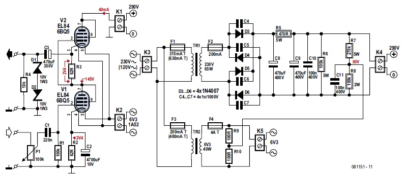
Before describing the circuit operation, it must be mentioned that construction of this circuit must not be attempted unless you have experience in working with tubes at high voltages, or can rely on the advice and assistance of an “old hand.” As a safety measure, two anti-series connected Zener diodes are fitted at the amplifier output. These devices protect the output (i.e., your headphones and ears) against possibly dangerous voltages at switch-on, or when output capacitor C3 breaks down.
The power supply is sized for two channels (i.e., a stereo version of the amplifier). The values in brackets are for Elektor readers on 120-V AC networks. Note the doubled values of fuses F1 and F3 in the AC primary circuits. The PSU is a conventional design, possibly with the exception of the 6.3-V heater voltage being raised to a level of about +80 V through voltage divider R7-R8. This is done to prevent exceeding the maximum cathode heater voltage specified for the EL84 (6CA5). R6 is a bleeder resistor emptying the reservoir capacitors C8 and C9 in a quick but controlled manner when the amplifier is switched off. Rectifier diodes D3–D6 each have an anti-rattle capacitor across them.
In the amplifier, assuming the tubes used have roughly the same emission, the half-voltage level of about +145 V exists at the junction of the anode of V1 and the control grid of V2. The SRPP is no exception to the rule that high quality, (preferably) new capacitors are essential not just for reproduction and sound fidelity, but also for safety.—Martin Louw Kristoffersen, Elektor, 081151-I, 7-8/2009
Kristoffersen used two EL84 (6BQ5) power pentodes in triode SRPP configuration. The EL84 (6CA5) is widely available and "forgiving of the odd overload condition." Two of the tubes are "SRPPed into an amplifier that’s intended to produce warm thermionic sound," he noted.
Editor's note: This article originally appeared in Elektor July/August 2009. audioXpress magazine and AudioXpress.com are Elektor International Media publications.