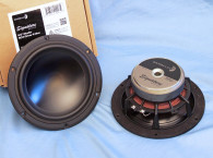

The cone assembly includes a black anodized aluminum moderately curvilinear cone and 2.4” diameter black anodized dust cap. Suspension is provided by 12mm wide and 6mm tall (NBR) surround plus a flat 105mm diameter Nomex spider with a linear roll configuration. This is connected at the neck joint to a vented 50mm diameter copper/zinc/aluminum (CZA) alloy former wound with round copper wire. Voice coil tinsel leads are stitched into the spider and terminate to a pair of chrome color coded push terminals.
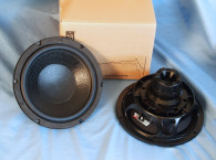
The FEA-designed motor structure incorporates a 109mm diameter × 18mm thick Y35 magnet sandwiched between the stunning milled and polished front plate and T-yoke. For additional cooling, the back plate (T-yoke) features a 20mm flared pole vent with six 3mm diameter peripheral vents. This motor also includes dual shorting rings (Faraday shields) comprised of an aluminum magnet ID ring and a copper pole cap (see the diagram in Photo 3).

Following my established protocol for Test Bench testing, I no longer use a single added mass measurement. Instead, I use the company’s supplied Mmd data (24.58 grams for the TM65 mkIV). I post-processed the 12 550-point sine wave sweeps for each TM65 mkIV sample and divided the voltage curves by the current curves to generate impedance curves. The phase was derived using the LMS calculation method, and I imported the data, along with the accompanying voltage curves, into the LEAP 5 Enclosure Shop software.
Because the Thiele-Small (T-S) data provided by most OEM manufacturers is generated using either the standard model or the LEAP 4 TSL model, I additionally created a LEAP 4 TSL parameter set using the 1V free-air curves. I then selected the complete data set, the multiple voltage impedance curves for the LTD model, and the 1V impedance curve for the TSL model in the transducer parameter derivation menu in LEAP 5 and created the parameters for the computer box simulations. Figure 1 shows the 1V free-air impedance curve. Table 1 compares the LEAP 5 LTD and TSL data and factory parameters for both samples.

LEAP parameter calculation results for the TM65 mkIV correlated well with the Stereo Integrity factory published T-S parameters, except for the 2.83V/1m sensitivity, which was higher than the T-S parameter calculated numbers. As usual in this column, I followed my established protocol and proceeded to set up computer enclosure simulations using the LEAP LTD parameters for Sample 1. Since this was intended for a car audio door mount acoustic environment, I programmed two closed-box simulations into LEAP 5 — one a higher Q Chebychev sealed box alignment (Qtc=1.0) in a 245in3 volume with 50% fill material (fiberglass), and the other a larger Butterworth (Qtc=0.7 target) sealed enclosure alignment with a 960in3 volume (also with 50% fiberglass fill material).

Figure 2 displays the results for the TM65 mkIV in the two simulated sealed enclosures at 2.83V and at a voltage level sufficiently high enough to increase cone excursion to Xmax+15%, which would have been 6.9mm, but I used the 70% of Bl number that Stereo Integrity uses, with is 7mm. The smaller closed box alignment produced a 3dB down frequency of 83Hz (F6=70Hz), Qtc=1.0 and the larger Butterworth alignment was –3dB= 66Hz (F6=53Hz), which turned out to be a somewhat higher Qtc=0.78.

Increasing the voltage input to the simulations until the maximum linear cone excursion criteria was reached resulted in 109dB at 27V for the smaller sealed box simulation and 103.5dB at 18V input level for the larger sealed enclosure. Figure 3 shows the 2.83V group delay curves. Figure 4 shows the 27V/18.0V excursion curves.


Klippel analysis for the TM65 mkIV woofer, performed by Patrick Turnmire at Redrock Acoustics on the DA2 analyzer, produced the Bl(X), Kms(X) and Bl and Kms symmetry range plots given in Figures 5-8. The Bl(X) curve for the TM65 mkIV (Figure 5) is symmetrical and typical of a relatively short Xmax small diameter transducer, accompanied by a very small amount of coil-out (forward) offset. Looking at the Bl Symmetry plot (Figure 6), the displacement is a meaningless 0.33mm at 6mm, the physical Xmax of this driver.


The Kms(x) Stiffness of Suspension curve (Figure 7)depicts a moderately symmetrical shape with a small amount of forward offset. Looking at the Kms symmetry range curve (Figure 8) shows a forward offset at the 3mm point of reasonable certainty of 1.2mm, decreasing to 0.94mm at the 6mm physical Xmax of the driver. Displacement limiting numbers calculated by the Klippel analyzer for the TM65 mkIV were XBl @ 82% Bl=4.3mm and for XC @ 75%, Cms minimum was 7.1mm, which means that for the TM65 mkIV, the Bl was the most limiting factor at the prescribed distortion level of 10%.


With the Klippel testing completed, I mounted the Stereo Integrity TM65 mkIV midbass woofer in a foam-filled enclosure that had a 15”×8” baffle. I measured the device under test (DUT) using the Loudsoft FINE R+D analyzer and the GRAS 46BE microphone (courtesy of Loudsoft and GRAS Sound & Vibration), both on- and off-axis from 200Hz to 20kHz at 2.0V/0.5m, normalized to 2.83V/1m using the cosine windowed Fast Fourier Transform (FFT) method. All of these SPL measurements also included a 1/6 octave smoothing. (This is done to match the resolution of the 100-point to 200-point LMS gated sine wave curves used in the column for several years.)
Figure 10 gives the Stereo Integrity TM65 mkIV’s on-axis response, indicating a moderately smooth rising response that is ±3dB from 300Hz to 3.5kHz with twin break-up modes located at 4.8kHz and 6.3kHz. Figure 11 displays the on- and off-axis frequency response at 0°, 15°, 30°, and 45°. The -3dB at 30° with respect to the on-axis curve occurs at 2.5kHz, so a cross point in that vicinity should be work well to achieve a good power response.


Figure 12 gives the normalized version of Figure 11. Figure 13 displays the CLIO horizontal polar plot (in 10° increments with 1/3 octave smoothing). And finally, Figure 14 gives the two-sample SPL comparisons, showing a close match (less than 0.5dB) up to 5kHz.


For the remaining series of tests on the Stereo Integrity TM65 mkIV, I fired up the Listen SoundCheck AudioConnect analyzer and SCM microphone (graciously supplied to Voice Coil magazine by the folks at Listen, Inc.) to measure distortion and generate time-frequency plots.
For the distortion measurement, I mounted the Stereo Integrity TM65 mkIV rigidly in free-air and set the SPL to 94dB at 1m (7.3V) using a pink noise stimulus. Next, I measured the distortion with the Listen microphone placed 10cm from the driver. This produced the distortion curves shown in Figure 15.

I then employed the SoundCheck software (V21) to get a 2.83V/1m impulse response for this driver and imported the data into Listen’s SoundMap Time/Frequency software. Figure 16 shows the resulting cumulative spectral decay (CSD) waterfall plot. Figure 17 provides the Wigner-Ville plot (chosen for its better low-frequency performance).


Looking at all the data for the new Stereo Integrity TM65 mkIV shallow-mount woofer, the performance looks good for a high-power handling 6.5” driver, especially one that is only 2.28” deep. For more information, visit the Stereo Integrity website at www.stereointegrity.com. VC
This article was originally published in Voice Coil, March 2024