The importance of measurement microphones for automotive testing is growing with new testing applications, the emergence of new automotive technologies, and the rise in consumer expectations for new infotainment options, improved calls, and active noise cancellation (ANC).
What Is a Measurement Microphone?
A measurement microphone is produced according to a standard, the IEC 61094. This defines basic microphone characteristics such as its physical dimensions, sensitivity, dynamic range limits, and more. IEC 61094 also provides tolerances for most specifications, and different methods for calibration. Finally, microphones are categorized depending on their size, specification tolerances, and sound field.
This standardization means that users can expect comparable performance from microphones of the same type. Using calibrated and standardized equipment and measurement procedures across different tests will yield reliable, repeatable, and comparable results.
Sound Fields
Measurement microphones are optimized to have a flat frequency response in ideal sound fields such as pressure field, free field, or diffuse field.
A pressure field is defined as the sound field on a surface or in a small, closed chamber, where the phase and magnitude are the same throughout. This could be the inside of a wind tunnel, small cavities, boundary layers, or acoustic couplers. Pressure microphones have a flat frequency response in a pressure field.
A free field is defined as a sound field without any objects that can introduce reflections. So, the only sound arriving to a microphone in this sound field is the direct sound from a source without the influence of any reflections. Free-field microphones have a flat frequency response in a free field when oriented at a 0-degree angle to the sound source.
A diffuse field, or random-incidence field, has sound arriving with equal probability, at any level and random phase, from all directions. It can be a room with many objects causing reflections in many directions. In practice, reverberant chambers for acoustic testing try to replicate a diffuse field within a limited frequency range. Diffuse-field microphones have a flat frequency response in a diffuse field.
Looking at these definitions in the majority of automotive testing scenarios, these ideal sound fields are not applicable. For example, a car cabin has both absorbing and reflective materials, making its sound field a cross between a free field and a diffuse field (Figure 1). Some cars have more reflective materials than others, causing differences from platform to platform. In addition, there can be multiple sound sources inside the car and not a single well-defined one, further contributing to the interior of the car not being an ideal sound field. When a measurement microphone optimized to have a flat frequency response in an ideal sound field is used in a nonideal one, the test results will have a certain amount of error. This error is difficult to estimate, because of the challenges of characterizing a nonideal sound field. As the frequency response of the microphone in this nonideal sound field is not fully known, it can be both over- and underestimated.

That is why standardized test equipment and measurement procedures are necessary—to overcome the problem of measurement error. If everyone uses the same measurement equipment and procedures, everyone gets the same measurement errors — making test results comparable. But there is a lot of work to be done in terms of standardizing measurement procedures in automotive testing. This makes the task of trying to reduce measurement errors from instrumentation important.
One way to reduce the measurement error is to minimize the microphone’s influence on the sound field. Any object placed in a sound field will have an influence on it—including a microphone. The larger the object, the larger the influence. So instead of a 1/2” microphone, a 1/4” microphone will cause less influence.
If a pressure measurement microphone is placed in a free-field environment pointing at a sound source with an ideal flat frequency response at zero-degree incidence (Figure 2), the frequency response test will still deviate from flat. This is because the acoustic waves from the sound source interact with the body of the microphone.

At low frequencies, the wavelength of the acoustical signal will be large compared to the size of the microphone, but at higher frequencies the wavelength will become shorter and shorter.
λ = c/f
where:
λ = Wavelength [m]
c = speed of sound [m/s]
f = frequency [Hz]
When the wavelength of the acoustic signal becomes comparable to the size of the microphone, interference and diffraction effects happen and the microphone will disturb the sound field. The disturbance is measured as a pressure build-up in front of the diaphragm (Figure 3). This pressure build-up is caused solely by the interaction between the microphone and the sound field, as the emitted sound signal shown in Figure 2 has a flat frequency response.

Per Rasmussen)
Another way of reducing the measurement error is to use a microphone with a frequency response that is optimized to be as flat as possible when the microphone is placed in a nonideal sound field. This is the basis for the multifield microphone concept. There is no official definition of a multifield microphone, but it can be considered a microphone with a relatively flat frequency response no matter which sound field it is placed in. Multifield microphones are not tuned to have a flat frequency response in an ideal sound field, but in a nonideal sound field (e.g., a sound field with characteristics that are somewhere in between a free field and a diffuse field).
Figure 4 shows the spread in frequency response from a GRAS 1/4” multifield microphone compared to a typical 1/2” free-field microphone. The black curve is the free-field response for each microphone, the blue one is the pressure response, and the green and red areas within those curves represent all frequency response variations possible when the microphone is used in nonideal sound fields.
The spread in frequency response is much smaller with the multifield 1/4” microphone thanks to its smaller size and the fact that its frequency response is tuned to be flatter when used in nonideal sound fields. The red curves on both graphs represent the frequency response tolerances established by the IEC 61672 sound level meter specifications standard and are there for reference. They indicate that with a 1/4” multifield microphone, test result uncertainties are reduced, and the frequency response is well within the IEC 61672 limits.

A common problem to consider with 1/4” microphones is that a small microphone will have a tighter diaphragm compared to the looser diaphragm of a larger microphone. Therefore, 1/4” microphones typically have lower sensitivity and higher noise floor than a 1/2” microphone. But smaller microphones will be able to withstand higher sound pressure levels than the larger ones. Figure 5 shows how microphone size is related to its dynamic range.

1/2” Microphones in Automotive Testing
One might think that every automotive test in a modern lab is performed with a 1/4” microphone. But in fact, most microphones used in automotive testing are 1/2” free-field microphones. There are many reasons for this:
History: 1/2” free-field measurement microphones are the most used microphones on the market across industries.
Comparable data: New test data often needs to be comparable with historical data. This makes test engineers stick with specific microphones, even when they know better microphones are available.
Dynamic range: Many automotive acoustic test applications could benefit from 1/4” microphones, but until very recently the noise floor of a 1/4” microphone was considerably higher than a 1/2” (Figure 6). This has led to the misconception that 1/4” microphones are not well suited for automotive applications.

AES Recommendations for In-Car Acoustic Measurements
In 2023, the Technical Committee on Automotive Audio from the Audio Engineering Society (AES) published a recommendation for In-Car Acoustic Measurements. The recommendation is a response to the lack of consensus in the industry on how to measure the essential attributes of in-vehicle audio systems. Without standardized methodologies, comparing different systems is almost impossible.
The recommendations are a first step toward creating common ground for this application. The first focus is on system level measurements where its basic attributes are measured, and the results can be used for comparing different systems. Measurements according to this recommendation can be used for alignment between vehicle manufacturers and their automotive audio systems suppliers, for comparing/benchmarking different platforms, and more.
Currently, the recommendation does not provide limits for the test results, so it cannot be used to qualify systems as good or bad, for example. But it is expected to evolve based on industry feedback.
The AES recommendation proposes a six-microphone H-array configuration placed in the different seats in the car (Figure 7) to measure parameters such as frequency response, maximum sound pressure level (SPL), and impulsive distortion using a pink noise (frequency response and max SPL), and a logarithmic sine sweep (impulsive distortion) reference signals.

To counter microphone interaction with sound fields, the AES recommends the use of 1/4” measurement microphones—in particular the new high-sensitivity 1/4” microphones.
1/4” High-Sensitivity Microphones: Setting a New Standard
1/4” microphones are better than 1/2” microphones because their smaller size lets them move their influence on the sound field to higher frequencies (Figure 3). But due to their smaller and tighter diaphragms, their sensitivity is lower. This means that a 1/4” microphone will have higher noise floor compared to a 1/2” microphone. Most 1/4” microphones have a noise floor of around 44dBA, compared to 17dBA to 20 dBA for 1/2” microphones.
Until recently, it was not possible to improve the noise floor of 1/4” microphones. But now, companies such as GRAS have introduced new high-sensitivity 1/4” microphones. These have a dynamic range more comparable to 1/2” microphones, but with the small-size advantage of reduced influence in the sound field. However, while typical 1/4” microphones can measure frequencies up to 70kHz to 80kHz, their high-sensitivity versions are usually limited to around 20kHz.
GRAS currently offers two different types of high-sensitivity 1/4” microphones: The pressure field GRAS 46BL-1 and the multifield 46BC (Figure 4). Figure 8 shows the noise floor difference between a typical 1/4” microphone vs. a high-sensitivity 1/4” microphone.

Figure 9 shows the dynamic range differences between different types of GRAS microphones including 1/2” pressure (P) and free field (FF), and 1/4” pressure (P), free field (FF) and multifield (MF).

Figure 10 illustrates the frequency range of various GRAS microphones. It shows that achieving the high sensitivity of the 46BL-1 and 46BC 1/4” microphones required a reduced frequency range compared to typical 1/4” models such as the 46BE and 46BD.

The high-sensitivity 1/4” microphones have been welcomed by automotive audio professionals. For example, the Automotive Acoustic Systems Engineering department at Harman International has chosen the GRAS 46BL-1 for calibrating their high-end vehicle sound systems because it has the lowest noise floor on the market (24dBA) while still maintaining a small form factor. An example of this is seen in Figure 11.

Trends Within Automotive Acoustic Measurements
So far, we have established the importance of using the right type of microphone for particular sound fields. We know that using a 1/4” microphone reduces the influence of the microphone in the sound field, and that a multifield version can also help reduce the uncertainty of test results when working in nonideal sound fields. Therefore, it is expected that 1/4” microphones will one day overtake 1/2” microphones in automotive testing. Finally, we have also seen that it is possible to overcome the 1/4” microphone’s high noise floor limitation by using high-sensitivity 1/4” microphones. But what if we want to measure sound pressure levels (SPLs) that are below the noise floor of 1/4” high-sensitivity microphones or regular 1/2” microphones?
Low-Noise Microphones
A low-noise microphone is a measurement microphone with a noise floor below around 15dBA. They have become more relevant in automotive testing with the introduction of electric vehicles (EVs), that lack a combustion engine to mask noise sources such as wind or road noise. EVs also have new, relatively low SPL noise sources at frequencies where the human ear is sensitive, such as the noise of the electric motors or inverter noise. Figure 12 shows how a low-noise microphone compares to a regular measurement microphone when it comes to inverter noise characterization.

Tougher Microphones
In automotive testing, microphones are often used on roads or test tracks, in temperature chambers, or close to heat sources. Most measurement microphones were not designed for such harsh treatment. To counter this, tougher measurement microphones with IP67 ratings (dust and water protection), and extended temperature ranges from -40°C and up to 125°C (-40°F to 257°F) have been introduced. Some microphones also have shock-absorbing designs to further protect them.
Examples include the GRAS 146AE, a tougher general-purpose 1/2” free-field microphone (Figure 13); the 147AX, a 1/2” surface-mounted pressure microphone with a compact design and magnetic mounting system (Figure 14); and the 147EB with three layers of protection, typically used for on-road brake noise testing and other extremely demanding environments (Figure 15).


Intelligent Microphones with Built-In Self-Verification
In applications such as automotive test cells, where verifying large numbers of channels quickly and efficiently is crucial, traditional measurement setups are often a hassle. The need to check hard-to-reach positions without physical interaction further complicates the process.
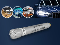
One possible solution is microphones with Syscheck2 self-verification technology. These intelligent measurement microphones can detect changes in channel sensitivity across multiple channels—a self-verification that is completed in seconds without any physical interaction.
Each Syscheck2 microphone contains a microcontroller with an oscillator to generate a reference signal (Figure 16). The system communicates through the standard TEDS interface via regular coaxial cable. A built-in light indicator shows the verification status: green for success and red for any detected issues.

Thinner Measurement Microphones
When measuring airflow and turbulence, the trend is also going toward smaller and thinner microphones to minimize microphone impact on air flow and measurements. Currently, the GRAS 48LA and 48LX-1 UTP (ultra-thin precision) microphones are the world’s thinnest measurement microphones at only 1mm thick (Figure 17). This makes them ideal for aeroacoustics applications such as wind tunnel testing or whenever a miniature measurement microphone is required due to space constraints (Figure 18).


Microphones with Built-In Digital Signal Processing
As auto and audio manufacturers increasingly use digital signal processing (DSP) to enhance in-vehicle sound systems with features such as in-cabin ANC, measurement microphone manufacturers are innovating to keep up. An example of this is GRAS EQset technology (Figure 19). Microphones with EQset use built-in DSP to equalize the frequency response of the microphone. This way, all microphones are born with the same sensitivity and flat frequency response, virtually eliminating the need for acoustical calibration. aX
www.grasacoustics.com


