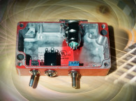
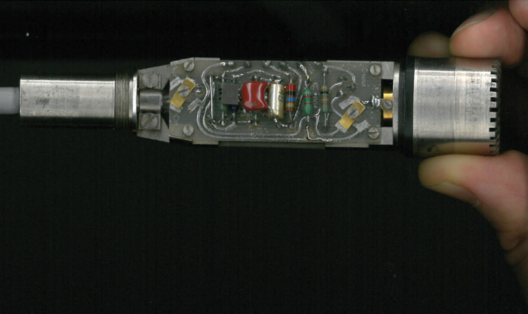
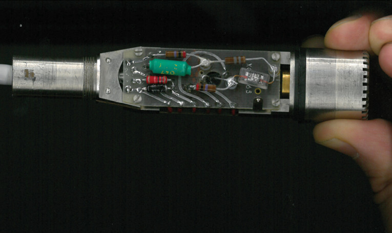
Many of these microphone systems have been appearing on the surplus market and some of them are appropriate to use for recording applications. To make any of these modifications you will need a temperature-controlled soldering iron and very good soldering skills, because the boards used on these microphones are delicate and have pads that lift easily. Photo 1 shows the top of the board and Photo 2 shows the bottom of the board. And, although we won’t be touching very much on the high-impedance input side of the circuit, careful flux removal will be absolutely essential. You will want to be using a good 63/37 rosin-core solder and a good quality flux remover spray such as the M-G Chemicals flux remover.
You will also need a good digital multi-meter (DMM) to make the various voltage measurements as well, with as high an input “ohms per volt” rating as possible. Because so little current is provided in these circuits, do not even think about using an analog meter or a $10 DMM.
The Microphone
What B&K means by “microphone” is just the bare microphone capsule itself with no electronics, so be aware of this when you look at these items. They have capsules for many applications, such as use in sealed chambers, and the response required differs in these applications.
The microphones you want for this project will be marked “free-field” meaning they are intended for flat response in open air far from the source. The 200 V capsules with this response would include the 4145 1” capsules and the 4133 or 4191 0.5” capsules.
There are prepolarized electret capsules such as the 0.5” 4189 that are suitable as well. They can be used with the same electronics although the polarization voltage will have to be turned off. However, they are more expensive and don’t show up as frequently on the used market.
In this article, we’ll be using a 1” system, so I selected the 4145 microphone. The 1” capsules are slightly directional at high frequencies, which I find to be of benefit for recording applications. They also have slightly better signal-to-noise ratio (SNR) than the 0.5” capsules.
It is possible by use of adaptors to put a 1” capsule on a 0.5” preamplifier body and vice-versa, but these adaptors are somewhat expensive and difficult to find. There are also many third-party “IEC Type I” measurement capsules that can work, from vendors such as Microtech Gefell, Rion, Norsonics, ACO, and so forth. Again, these are all fine as long as you get free-field versions, and they will all interoperate perfectly well with the B&K components.
The 2627 “Preamplifier”
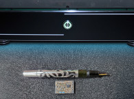
B&K uses the word “preamplifier” to mean the microphone electronics, what we might call the “body” or “handle of the microphone.” I chose the 2627 1” preamplifier because it is large and easier to work inside, and because I prefer the 1” capsule (see Photo 3). These are also among the more common preamplifiers on the surplus market today.
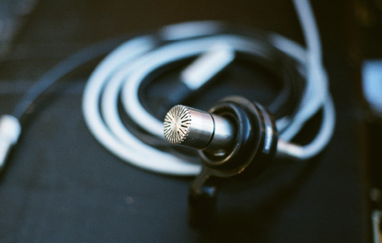
Figure 1 shows the schematic of the 2627. The capsule is supplied with 200 V through R1 and R9, which provides the static polarization on the diaphragm. As the diaphragm moves in and out, the capacitance varies and, therefore, the voltage at that point changes.
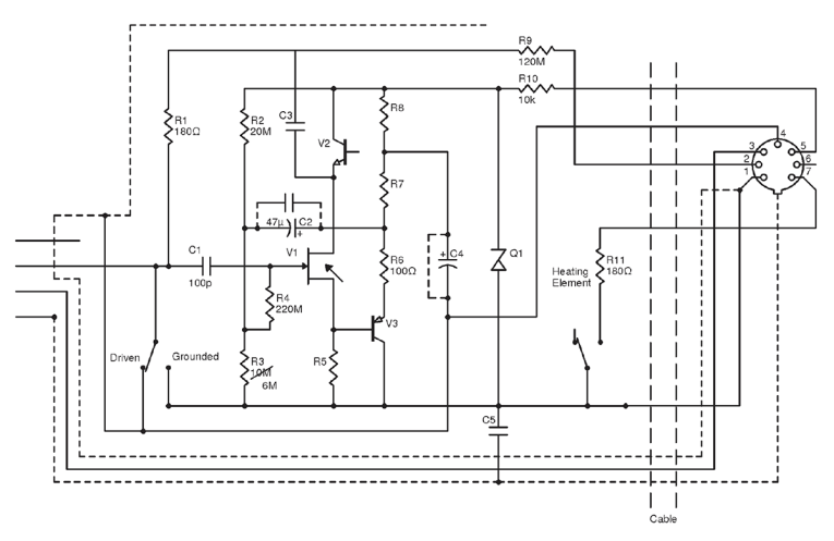
The AC part of the changing voltage goes through a glass capacitor, C3, and into the gate of the FET V1, which acts as a cathode follower. V2 acts as a constant current source to linearize the FET.
The output of the FET goes into the PNP transistor V3, which again is acting as a follower. It’s a little hard to see that at first because it’s upside-down compared with an NPN follower. The output goes into a resistive divider, which supplies feedback to the input through C2, and a signal to the output and to the shield around the capsule through C4.
So, what can be done to make this design more suitable for recording applications? First it’s important to look at things that aren’t necessary. That Zener diode, D1, is a 130 V Zener that is always reverse-biased and never turned on in normal operation (it’s for protection purposes only), so it’s never adding any noise and can be ignored. Those high-valued resistors, R1 and R9, look like they might be big noise sources, but they are in parallel with a big shunt capacitor anyway (namely the capsule) so they really have no noise contribution to speak of.
The major noise sources in this device are the semiconductors, and the biggest contributor there is V1. It’s well worth the trouble to replace V1 with a Toshiba 2SK170BL FET, if you can get one. There is a company that is second sourcing the now unavailable Toshiba part, but the replacement is not as quiet as the original component.
To make the 2SK170BL work in place of the original FET, the bias point needs to be altered as well, by changing R3 from a 20 M resistor to a 6.2 M resistor. This moves the quiescent voltage on the FET from 14 V above ground down to around 9 V above ground. R5 holds the source of the FET about 5 V above ground so we would consider that a VBS bias change from 9 V to 4V, which is necessary for the different requirements of the 2SK170BL FET.
Now, it’s worth looking at all of the capacitors in the signal path. There are really only three of them. The first one C3, is a high-grade glass capacitor, which should be left in place unchanged. The second one, C2, is the feedback capacitor. It is a tantalum capacitor with a considerable amount of DC across it, so it’s never near the zero crossing region. In addition, it is a huge value compared with the load impedance of the input stage, so there is hardly any ripple across it. Both of these things mean it contributes very little distortion to the system. Still, you can add a 0.1 µF film capacitor across it, just tack soldering it above the existing tantalum capacitor, if it makes you feel better. You don’t have to do it, and I don’t hear any difference doing it, but the bypass capacitor might reduce distortion products a little bit. I do it.
Where the problems begin are with C4, the output coupling capacitor. It’s away from the zero crossing by about 6V, but there is a considerable current going through it. The distortion would benefit from replacing it with a much larger tantalum or aluminum electrolytic, or with a film capacitor. Neither one of these, though, will physically fit.
What if we replace the capacitor with a dead short, though? The shielding around the capsule is driven from that output to provide capacitive compensation and improve high frequency response, but if the capacitor is removed the shield is just shifted 6 V, which really does no harm. The output is shifted by 6 V too, but that can easily be fixed by putting a DC blocking capacitor inside the power supply where there is plenty of room for it.
The downside of doing this is that changing that DC voltage on the compensation ring on the capsule will change the capsule sensitivity a tiny bit. Not enough to worry about for recording work, but enough that it’s no longer acceptable as a calibrated source for measurement work where measuring absolute signal intensity is important. So, it would be good to mark the body to indicate this.
The 2804 Power Supply
The 2804 power supply for these microphones is a free-running flyback oscillator, used to step the output of three D batteries. The supply itself is good and the oscillator should run slightly over 20 kHz and be inaudible.
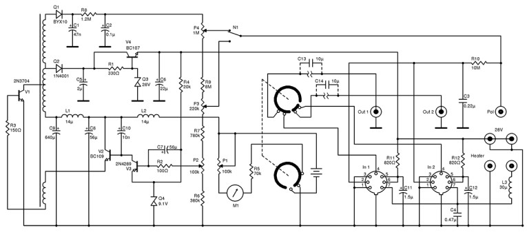
The only change needed for the power supply itself is to add a 10 µF film capacitor between pin 4 of the microphone input plugs and the switch (see Figure 2). This will block DC that appears as a result of the microphone capacitor being removed. This is in the signal path directly and it’s worth the cost to use a high-grade capacitor.
However, while you have the case open, pre-emptively replace the electrolytic capacitors C6, C7, C8, and C9. You may also wish to replace the tantalum decoupling caps C11 and C12. Being on the primary side, C8 and C9 have only 4.5 V across them and can be replaced with 10 V radial capacitors. C7 can have considerable voltage briefly on startup and should be a 25 V capacitor. C6 has 28 V and should be rated for 35 V. Likewise C11 and C12 should be replaced with axial tantalum or aluminum electrolytic caps, 2.2 µF at 35 V.
If you hear an audible whistle from the supply, it is mostly likely the frequency being pulled down by excessive load from C6, C11, and C12 being bad. Replace all the electrolytics mentioned above, plug in the microphones, and give it about five minutes to stabilize. Then, measure the 28 V output voltage from the rear panel connector and adjust the trimmer pot P2 until it is correct. Measure the polarization voltage on the back, and adjust P4 until it is right on 200 V. If it won’t go over 30 V or so, you have N1 in the wrong position.
That’s it for the power supply. Now, there are some other model power supplies that will work with this system (e.g., the 2807 line-operated supply). But, I haven’t worked with those and prefer the freedom of battery power, so you are on your own as far as putting blocking capacitors in and cleaning up the old capacitors.
The Output Cable
Now, the outputs of these microphones are unbalanced, and the output coming out of the power supply is on a weird B&K shielded-banana-style plug. There are some B&K connector-to-BNC adaptors out there, but that’s not what I would recommend.
You want to get the B&K connectors themselves, and you want to have a balanced audio line going into them with an XLR connector. Pin 1 from the XLR goes to the cable shield, which goes to the B&K connector shield. Pin 2 from the XLR goes to one of the twisted pair, and into the center conductor of the B&K connector. Pin 3 from the XLR connector goes to an 47 Ω resistor and then to the B&K connector shield. This matches the output impedance of the microphone, so when the microphone is powered up both legs of the balanced pair see the same source impedance, and it truly is balanced and the noise is cancelled out. (The interesting thing about this approach is that it is severely unbalanced when the microphone is turned off and the output impedance is effectively very high, so you’ll hear a lot of noise in some cases, but it will completely disappear when power is applied to the microphone).
Operation
If you are fond of widely spaced microphones such as a spaced triad oar widely-spaced pair, these are a reasonable choice. However, the slight directionality at high frequencies may require them to be pulled back a bit more than a smaller diaphragm omni.
That same beamyness inherent in the 1” capsules is not enough to use in a Decca tree without adding some balls to the body, but with a small wooden ball behind the capsule, these microphones can work very well in a Decca tree arrangement. These also are a very fine choice for baffled omni configurations, and again the slight high frequency directionality means they can be cocked outward slightly to give a little more amplitude difference at high frequencies. I have used both a Jecklin disc and a smaller-sized baffle made from a mouse pad over the course of many years and been pleased with the overall sound.
The top end on these microphones is clear and extended but without a sense of artificiality. High frequency percussion comes across as being very realistic. The low end is extremely detailed and the –3 dB point is down around 2 Hz (although that can be restricted by the input impedance of the microphone preamp you’re using and the output blocking capacitor). The low-end extension can often be a problem. I have seen instances where they accurately picked up low-frequency rumble from things such as air currents caused by candles at chamber concerts. Having 20 bits of dynamic range for digital recording means you can afford to throw some of them away and filter the noise later, but you may find a high-pass filter on recording could still be of benefit in some cases. Should you need a windscreen, and someday you will, the WindTech US-1 windscreen will fit on the 1” measurement microphones.
Peroration
Years ago I became a great fan of using measurement microphones for recording work. Over the years, I have tried a several modifications as part of the process of adapting them to recording work. The majority of changes I made were suboptimal and it took me a couple decades to get to the point where I was happy with the results and found the basic arrangement convenient, clean-sounding, and easy to use. I hope that this information is of benefit to people interested in adapting these microphones to recording use (see Photo 3).
There have been several manufacturers making commercial microphones that use some variety of measurement capsules and electronics capable of phantom powering. As far as I know the only device capable of powering the externally-polarized measurement capsules from phantom power is the Josephson C617. Similar microphones using the electret measurement microphone capsules include the Sonodore RCM-402 and the ACO 4048. The Chinese company MicW has also attempted to make such devices although I am not familiar with its calibration process.
I have only fine things to say about the basic concept and the B&K implementation, and if you are looking for a clean, slightly beamy omni with detailed, but not artificially crisp top and and very deep low end, I recommend these microphones. aX
This article was originally published in audioXpress, July 2016.