
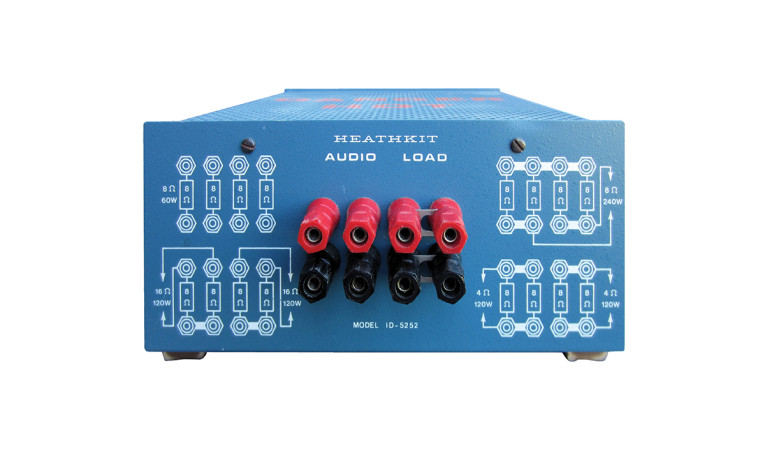
It’s been a quarter century since the Heath Co. got out of the kit business. And, although most types of test equipment once offered by Heathkit can be purchased factory-assembled from countless manufacturers, no one seems to be making an audio load. If you need one, you’ll have to roll your own.
(As an aside, Heathkit re-emerged in 2013, and currently offers an AM radio kit, a 2m amateur radio antenna, and upgrades to a few of its old products, including the IG-18 Audio Generator and the AJ-1510 FM Tuner. I don’t know how many electronics enthusiasts will pay $150 for an AM radio with no dial calibration and no speaker, but I wish the company well.)
Audio Load Parts
Fortunately, the raw parts for building an audio load are easy to find. Parts Express carries 4Ω and 8Ω load resistors designed specifically for audio testing. They are available in 100W and 200W power ratings, and are reasonably priced. The resistors are manufactured by Loyal Machinery and Electronic Co. Ltd., (LMEM) in Taiwan, and are part of the company’s MH-series. The specific type carried by Parts Express is the MHNL. The “N” indicates non-inductive and the “L” indicates that the resistor has flying leads rather than terminals.
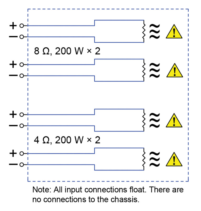
Figure 1 shows the schematic diagram for the dummy load. To me, it made sense to go with the 200W resistors — two at 4Ω and two at 8Ω, for a total of four resistors. Parts Express specifies 5% tolerance for these resistors. Using my B&K Precision 879B LCR meter, I measured the actual resistance for the four samples at 4.072 Ω, 4.078 Ω, 7.956 Ω, and 8.034 Ω, for tolerances of 1.8%, 1.95%, 0.43%, and 0.55%. B&K Precision specifies an accuracy of 2% for single-digit resistances, so the LMEM resistors are well within tolerance. Parts Express claims that the resistors are non-inductive, and measurements with the B&K Precision meter show the inductance to be very low on the 200W versions: 20 µH for the 8Ω resistors and 14.5 µH for the 4Ω resistors. The inductance changes no more than 0.5 µH as the test frequency is varied between 100Hz and 10kHz. The very low inductances are reflected in the 10kHz impedance measurements, which are within 0.1 Ω of the resistance measurements.
Heatsinking
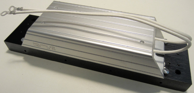
Each resistor is encapsulated in its own heavy, aluminum heatsink, and various notes on the Parts Express website indicate that they can be used without any additional heatsinking. However, this isn’t true if the resistors are to be used at or close to full power for extended periods, so I added an additional heatsink to each of the four resistors in my dummy load. Parts Express carries an anodized aluminum heatsink that’s convenient for this purpose — Sure Electronics’ DC-HS11123. The Sure heatsink comes with a lot of extra hardware that’s not needed for this project, including eight mounting brackets, two bags of machine screws, and an acrylic LED diffuser panel. All you need for one resistor is the heatsink and four of the metric number 3 mm × 8 mm machine screws, plus four 6/32 × 1/2” machine screws available at your local hardware store.
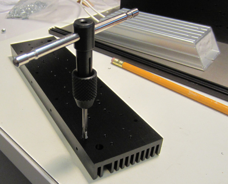
The Sure heatsink has a proliferation of holes tapped for the metric number 3 machine screws. The only ones needed for this project are four along one edge of the heatsink, which will be used to mount the heatsink/resistor assemblies to the chassis bottom plate. The heatsink also has four untapped holes on the large, flat side, which are exactly the right size for a 6/32 tap. I used these to secure the resistors to the heatsinks, using 6/32 × 1/2” panhead machine screws.
In addition to the right size hole, the key to success in tapping aluminum is to use a high-quality tap. This is no place to look for a bargain. Cheap taps are prone to breaking, and once a tap breaks, the end stuck in the metal you’re tapping will be very difficult to remove. At that point, you’re likely to utter colorful language inappropriate for polite company (I speak from experience!). Irwin/Hanson taps are high-quality, American-made tools that are available at all the major hardware stores. If you live outside the US, you can use a metric 3.5 mm × 0.6 mm tap and machine screws instead of 6/32.
One edge of the resistor will be flush with one edge of the heatsink — this is the side that will be mounted to the bottom plate of the enclosure. The opposite resistor edge with extend about 1/8” beyond the other edge of the heatsink. You’ll need to file four notches in the beveled edges on the wider side of the resistors to provide clearance for the 6/32 machine screws (see Photo 2). Use a round file and file just enough for the screws to clear. When the machine screws are tightened, one edge of each screw head will secure the resistor to the heatsink. You can substitute a flange-head or button-head machine screw — the built-in washer on these types will give you a little more bearing on the resistor case. However, I had no problem securing the resistor to the heatsink with panhead screws. Do a “dry run” to make sure everything fits properly. An alternate method of mounting the heatsinks would be to use the two large notches on the ends of the resistor case. But, this will require drilling holes in the heatsink.
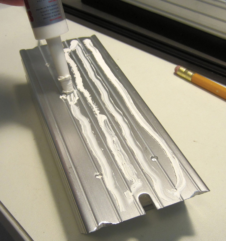
Next, apply a thin layer of thermal compound to each resistor (see Photo 3), and mount the resistor on the heatsink. I used white, silicone-based thermal compound impregnated with zinc oxide. Rawn 10004 Silicone Heat Sink Thermal compound is rated for temperatures as high as 260ºC (500ºF), and is available from MCM Electronics. Similar products are available from a variety of electronics suppliers. The trick during application is to use enough so the compound will ooze into the grooves of the resistor body when the resistor is tightened against the heatsink. This will maximize thermal transfer. If you’re in doubt, fill each groove first. If you apply to much compound, you’ll need to wipe off the excess after tightening the screws. Photo 4 shows a completed resistor/heatsink assembly.
Modular Enclosure
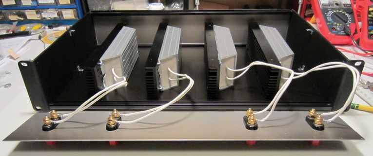
My favorite enclosures for audio projects are the modular aluminum types made by Wolgram Engineered Plastics, also sold by Markertek under the Connectronics brand. These are the same enclosures that were made by Sescom back when it was run by the late Franklin Miller. I used the 2RU10 Rack Chassis for this project. If you don’t want or need the rack ears, try the MC-20A instead — it has the same internal dimensions.
The resistor/heatsink assemblies should be secured to the chassis bottom plate with four of the metric number 3mm × 8mm machine screws supplied with each heatsink. I used five-way binding posts mounted on the front panel for the connections to the resistors.
Photo 5 shows the final assembly of the dummy load, with the four resistor/heatsink assemblies mounted on the bottom plate, and the resistor leads secured to the binding posts. The resistor leads are not polarized, but in the interest of neatness, connect the bottom resistor leads to the bottom (black) binding post terminals. Note that the resistor leads are connected only to the binding posts. All connections float, and there are no connections to the chassis.
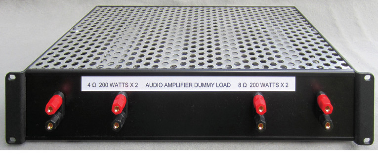
The solid top plate of the Wolgram/Connectronics enclosure won’t provide any ventilation for the resistors, so I replaced it with a piece of perforated aluminum. The Small Parts 3003 perforated aluminum sheet, available from Amazon, is the same thickness as the 2RU10 and MC-20A top plates — 14 AWG. You’ll have to cut it to fit, and secure the center brackets on the sides of the case using small fender washers along with the supplied machine screws.
Each resistor flying lead has two solid conductors covered with insulation designed for high-temperature applications. Nonetheless, I think it’s prudent to avoid having the resistor leads touch the resistors or the heatsinks. Fortunately, the leads are stiff enough that you can easily dress the leads between the resistor/heat sink assemblies when you secure the front panel in position.
Photo 6 shows the completed audio dummy load. Having one pair each of 4Ω and 8Ω resistors is ideal for my own needs. However, you may use any combination that suits your own needs. Following Heathkit’s approach, you can create a variety of load values using series and parallel combinations.
Testing
Most readers probably don’t need a lesson in Ohm’s Law, but it’s a bit sobering to consider the demands made on an amplifier and a load resistor at a power level of 200W. To dissipate 200W into 8Ω, an amplifier must deliver 40 VRMS to the load at a sustained current level of 5A. This is no mean feat. In addition, dissipating that much power into a load resistor will generate considerable — indeed, potentially dangerous — levels of heat. These resistors appear designed for heavy duty use, but user caution is mandatory.
The LMEM datasheet for the MH200 lists a chassis-mounted surface temperature specification of 240ºC (464ºF) at full power, and a chassis-mounted load rating of 1.5 hours ON followed by 0.5 hours OFF, repeated for 1,000 hours. The specified chassis is 300 mm × 300 mm, 3 mm thick, which is a sizable chunk of metal. You’ll never achieve this level of chassis heatsinking if you mount four resistors in a reasonable-size enclosure, which is why I believe that additional heatsinking is important.
I tested one of the 8Ω resistors at its full power rating for 5 minutes, using a QSC RMX 1450 professional audio power amplifier and my Fluke 62 Mini Infrared Thermometer. The RMX 1450 is a pro-audio workhorse rated at 280 WRMS per channel into 8Ω, so it had no problem delivering 200W into the load resistor. After 5 minutes at 200W, the resistor measured 93ºC (200ºF) on both the side and the top of the metal resistor case. The corner (edge) of the resistor case was a bit hotter, at 102ºC (215ºF). The heatsink measured 91ºC (195ºF) along the edge and in the middle of the fins, which indicates good heat transfer from the resistor to the heatsink. My temperature readings are well below the manufacturer’s data, but I didn’t run the test any longer. If I had, the temperature would have continued to rise well beyond my own comfort level. Immediately after disconnecting the resistor from the amplifiers, the resistance measured 8.02 Ω (LMEM specifies the temperature coefficient as ±260 ppm/ºC MAX).
The 93ºC measured after 5 minutes is a considerable amount of heat — nearly hot enough to boil water — and the manufacturer’s specification of 240ºC is well into solder-melting territory. Even if a resistor is designed to withstand such temperatures, other things in its vicinity, including the human performing the test, probably aren’t. Exercise extreme caution when making high-power measurements — the risks of fire and personal injury should NOT be taken lightly. As is the case with your kitchen stove and outdoor grill, safety is ultimately in the hands of the operator.
I don’t foresee the need for continuous operation at the full power rating of these resistors. If you do, you should strongly consider fan cooling and possibly larger heatsinks. The heatsink fin orientation should be in the direction of the air flow from the fans. The horizontal fin orientation in my layout is ideal for mounting up to four small “muffin”-type fans on the back of the enclosure. A perforated bottom plate with extra-long feet will further improve air circulation through the enclosure and increase the distance between the bottom plate and the adjacent surface. The perforated bottom plate may require some reinforcement to support the weight of the four resistor/heatsink assemblies.
Resources
Heathkit, www.heathkit.com
Loyal Machinery and Electronic Co., Ltd. (LMEM), www.lmem.com.tw/product-en.html
MH-series datasheet, Loyal Machinery and Electronic Co., Ltd. (LMEM), www.lmem.com.tw/PDF/Silver%20Metal-Clad%20Wirewound%20Resistor.pdf
Markertek Video Supply | www.markertek.com
MCM Electronics | www.mcmelectronics.com
Parts Express | www.parts-express.com
Wolgram Engineered Plastics, LLC | www.wolgrammfg.com
This article was originally published in audioXpress, March 2017.