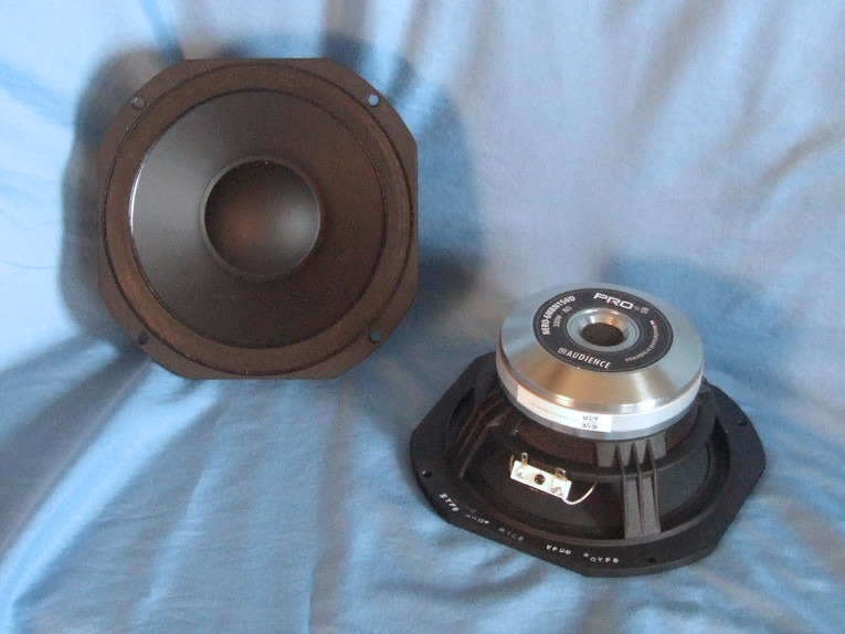
The driver SB sent to this Test Bench is a new 6.5” pro sound midrange from the new SB Audience OEM NERO product line, the NERO-6MRN150D (see Photo 1). In terms of the NERO-6MRN150D’s feature set, the frame is a proprietary four-spoke-cast aluminum frame, and includes four 40 mm × 12 mm screened vents below the spider (damper) mounting shelf. Additional cooling is provided by a 20 mm diameter pole vent with a 26 mm flared exit.
The cone assembly consists of a curvilinear paper/graphite composite cone and a 60 mm (2.25”) diameter convex paper dust cap. Compliance is provided by a flat foam surround in the tradition of the Audax PR170 or some of the early PHL mids, while remaining compliance comes from a 3.75” diameter elevated cloth spider with constant height waves.
The motor design on NERO-6MRN150D utilizes a neodymium ring magnet fitted with an aluminum shorting ring (Faraday Shield). The NERO-6MRN150D’s neodymium ring magnet motor was FEA-designed using a 49.5mm (1.95") diameter voice coil wound with round copper-clad aluminum wire (CCAW) on a non-conducting glass fiber (Til) former. The neodymium ring magnet is sandwiched between a milled front plate and a milled and shaped back plate. Last, the voice coil is terminated to standard solderable terminals.
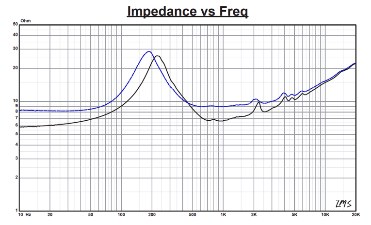
I began testing the NERO-6MRN150D using the LinearX LMS analyzer and VIBox to create both voltage and admittance (current) curves with the driver clamped to a rigid test fixture in free-air at 0.3, 1, 3, 6, 10, and 15V. However, it become apparent that this midrange is so stiffly suspended that increasing the voltage does not cause the voice coil to ride out of the gap. Figure 1 shows the comparison of the 1V impedance (solid black curve) to the 15V impedance (blue dashed curve), and except for a minor amount of resonance shift, the resonance shape remains fairly constant. This behavior rather invalidates the LTD parameter measurement model, and indeed the Thiele-Small (T-S) parameter results for the multi-voltage testing did not correlate closely to the factory data. After this observation, I decided to keep with the more conventional single voltage (1V) TSL modeling data for the enclosure simulation.
Following my established protocol for Test Bench testing, I no longer use a single added mass measurement and instead use the physically measured Mmd data (14.1 grams for the NERO-6MRN150D). The collected data, in this case the two 550-point 1 V sine wave sweeps for each NERO-6MRN150D sample, were post-processed.
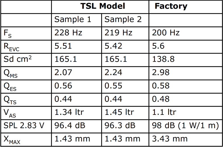
I then divided the voltage curves by the current curves to generate impedance curves, derived the phase using the LMS calculation method, and imported the data, along with the accompanying voltage curves, to the LEAP 5 Enclosure Shop software. Again, for the reasons stated earlier, I did not use the LTD modeled T-S parameter data, but only the 1V TSL modeled T-S parameter data. The 1V TSL data was selected in the transducer parameter derivation menu in LEAP 5 and the parameters created for the computer box simulations. Table 1 compares the LEAP 5 TSL data and factory parameters for both of NERO-6MRN150D samples.
LEAP TSL parameter calculation results for the NERO-6MRN150D correlated moderately well with the factory published data, except for the Xmax numbers. SB uses its own definition of Xmax, which is why it’s different. Standard practice and what you will find in my book (The Loudspeaker Design Cookbook) is Xmax= (Hvc-Hg)/2, so with a voice coil length of 8.85 mm and a gap height of 6mm, Xmax is 1.43mm. SB Audience uses same formula that Faital Pro does where Xmax = (Hvc-Hg)/2 + Hg/3, so it would be 1.43mm plus 2mm (Hg/3), which is why the company publishes Xmax for this driver at 3.43mm.
This actually is a somewhat similar fringe field compensation factor to what I do in finding the maximum SPL of a driver in a LEAP 5 box simulation when I raise the input voltage until the excursion maximum is Xmax + 15%, which for the NERO-6MRN150D is 1.64mm, but even that is more conservative than SB or FaitalPro’s Xmax definition. (The Xmax + 15% comes from Mark Gander’s work at JBL Pro some years ago, and it is based on excursion beyond Xmax producing 3% THD.)
SB also uses a more conservative Sd number of 136.8 cm2 compared to the 165.1 cm2 used in my work, which is derived from the cone diameter plus 50% of the surround width on each side of the assembly. This difference in methodology affects the Vas calculation somewhat. However, I followed my established protocol and set up computer enclosure simulations using the LEAP TSL parameters for Sample 1.
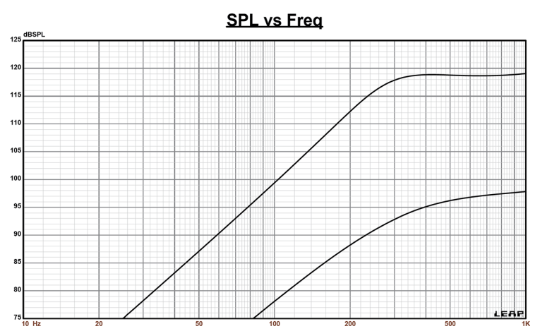
This also turned out different from expected for this driver. LEAP 5 predicted a sealed box Butterworth Qtc = 0.7 to be about 43 in3, however, the smallest box you can physically build for this driver with a minimum height and width plus a depth equal to the depth of the driver plus 0.5” relief for the rear vent is 106 in3 (5.5” × 5.5” × 3.5”) with 50% fill material (fiberglass), so this was the volume used for the single sealed box simulation done for this driver. Please note that this driver is not intended for use in its “piston” range, so box volume is not particularly relevant. However if you are designing a passive bandpass filter for this driver in a three-way system, knowing the frequency and Qtc of the driver impedance is useful.
Figure 2 displays the results for the NERO-6MRN150D in the single sealed enclosures at 2.83 V and at a voltage level sufficiently high enough to increase cone excursion to Xmax +15% (1.61mm). This produced a F3 frequency of 274Hz (F6 = 213Hz) with a Qtc = 0.54 for the sealed enclosure.
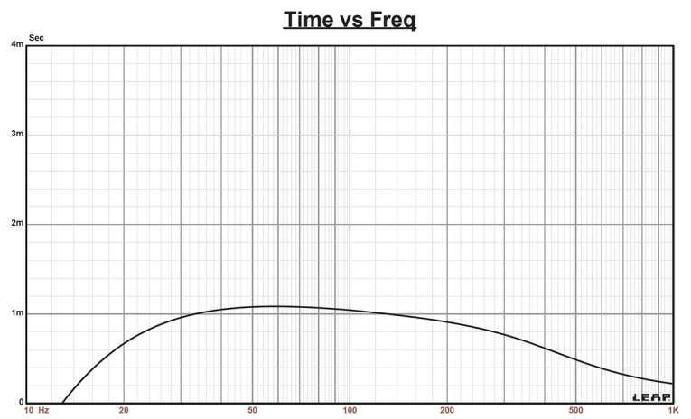
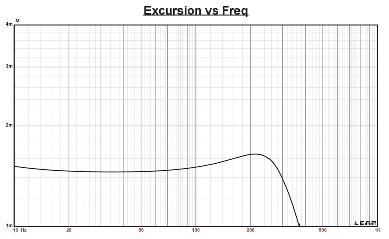
Increasing the voltage input to the simulations until the maximum linear cone excursion criteria was reached resulted in 119 dB at 70 V for the closed box simulation. Figure 3 shows the 2.83 V group delay curves. Figure 4 shows the 70 V excursion curve. Again, since this is a midrange driver, the device will most likely always have a high-pass that will keep the driver from ever operating in its piston range, which is typical for most midrange drivers—home or pro. As such, this data is only offered from the perspective of passive network design.
Previous midrange driver explications have sometimes featured Klippel analysis as part of the report, however, for the same reason that the LEAP 5 LTD model would not be useful on this midrange, Klippel analysis would also not reveal much useful information, at least from the standpoint of Bl and Kms curves that you normally see in these performance reviews. As such, this information is not included in the report on the NERO-6MRN150D this month.
For the remaining test procedures, I mounted the NERO-6MRN150D in a foam-filled enclosure that had a 15" × 8" baffle and then measured the device under test (DUT), using the LoudSoft FINE R+D analyzer and the GRAS 46BE microphone (courtesy of LoudSoft and GRAS Sound & Vibration) both on- and off-axis from 200 Hz to 20kHz at 2.0V/0.5m, normalized to 2.83 V/1m using the cosine windowed Fast Fourier Transform (FFT) method. All of these SPL measurements also included a 1/6 octave smoothing.
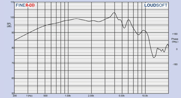
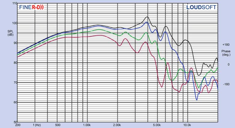
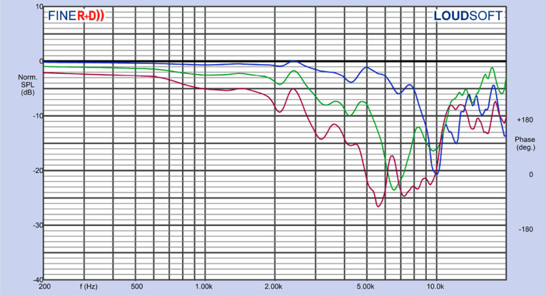
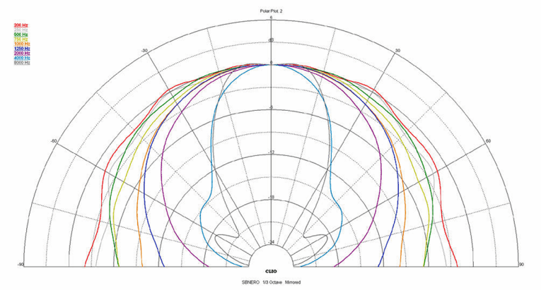
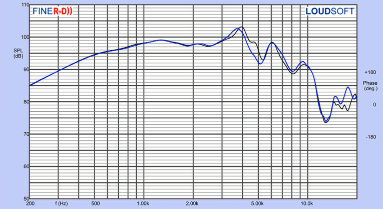
Figure 5 gives the NERO-6MRN150D’s on-axis response, indicating a fairly smooth rising response with no breakup modes or peaking out to about 3 kHz, with a peak in the response at 4kHz where the driver begins its low-pass roll-off. Figure 6 displays the on- and off-axis frequency response at 0°, 15°, 30°, and 45°, showing somewhat more directivity than most home audio 6" midwoofers. At -3dB at 30°, with respect to the on-axis curve, occurs at 2.7kHz, so a cross point in that vicinity should work well to achieve a good power response. Figure 7 gives the normalized version of Figure 6, while Figure 8 displays the CLIO horizontal polar plot (in 10° increments). And finally, Figure 9 gives the two-sample SPL comparisons for the NERO-6MRN150D, showing a close match (less than 0.5 dB) throughout the operating range.
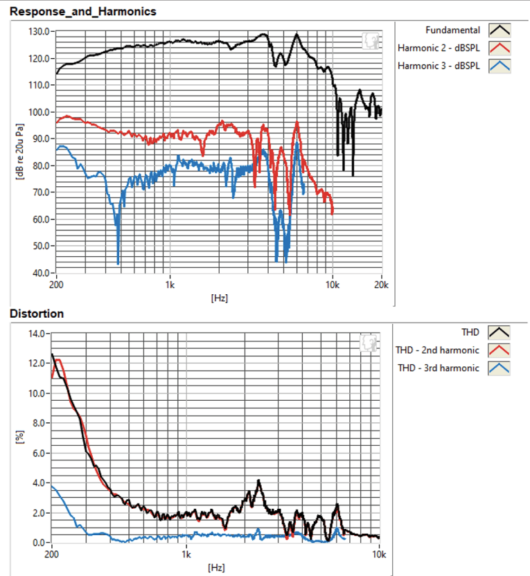
For the remaining series of tests on the NERO-6MRN150D, I employed the Listen, Inc. SoundCheck AudioConnect analyzer and SCM microphone (graciously supplied to Voice Coil by the folks at Listen, Inc.) to measure distortion and generate time-frequency plots. For the distortion measurement, I mounted the 6” driver rigidly in free-air, and set the SPL to 104 dB at 1 m (7.53 V) using a pink noise stimulus. Then, I measured the distortion measured with the Listen, Inc. microphone placed 10 cm from the driver. This produced the distortion curves shown in Figure 10.
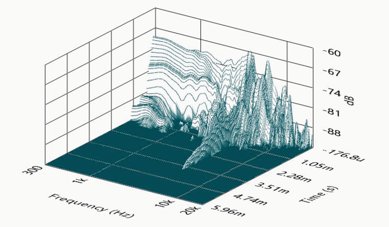
I then employed the SoundCheck software to get a 2.83V/1m impulse response and imported the data into Listen’s SoundMap Time/Frequency software. Figure 11 shows the resulting cumulative spectral decay (CSD) waterfall plot. Figure 12 shows the Wigner-Ville plot (chosen for its better low-frequency performance).

Looking at all the data for the NERO-6MRN150D, and considering its high 98dB 1W/1m sensitivity and 150W AES power rating, along with the outstanding build quality of this product, this should be an effective pro midrange, especially with an electronic crossover and DSP, which would likely be a typical application. For more information, visit the SB Audience website at www.sbaudience.com. VC
This article was originally published in Voice Coil, November 2020.


