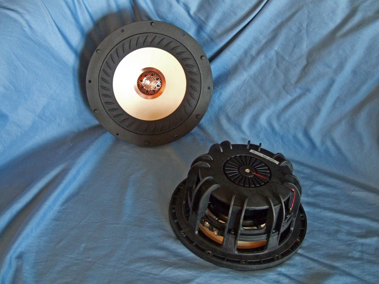
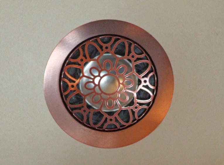
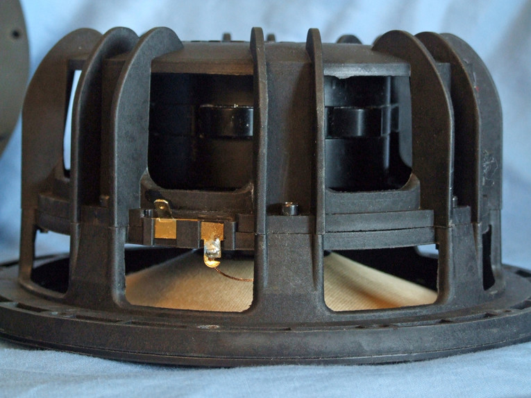
The subject of this explication is a new coaxial design in that vein recently released by TB Speaker, the W8-2314 (see Photos 1-3). In terms of features, the W8-2314 is built on an eight-spoke two-part ABS injection-molded frame that incorporates a separate injection-molded trim ring. Cooling for this driver is provided primarily via the completely open area below the spider (damper) mounting shelf. Incorporated into the frame is the underhung type woofer motor that consists of a circular array of six neodymium slugs—an arrangement that makes room for the concentrically mounted 25 mm tweeter and tweeter rear cavity.
This multi-neodymium magnet underhung motor drives a 44.43 mm diameter voice coil wound with round copper wire on an conducting aluminum former glued to a moderately curvilinear bamboo fiber paper cone. Compliance for this driver is rather unique. The NBR/CBR surround has a primarily flat profile articulated with a series of oval reliefs on its surface. The spider is also unconventional and consists of a 3.5” diameter NBR/CBR flat profile with no waves, so more like a small flat surround. All this is terminated to gold terminals located on opposite sides of the frame to discourage rocking modes.
The tweeter dome is a 25 mm aluminum/magnesium alloy inverted type suspended with a black NBR/CBR surround that has similar oval reliefs around its perimeter. This high-frequency device incorporates a neodymium slug with a low resonance rear cavity as well as a copper-colored decorative protective grill with gold plated terminals located between the two woofer terminals. With all of this taken together, I would have to say that TB Speaker’s W8-2314 coaxial is as unique a design as I have encountered in quite some time.

black solid = sealed at 23 V; blue dash = vented at 27 V).
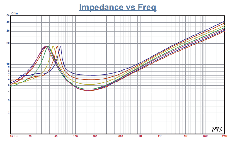
Testing began with the woofer half of this coaxial driver. I used the LinearX LMS and VIBox to produce both voltage and admittance (current) curves with the driver clamped to a rigid test fixture in free-air at 0.3V, 1V, 3V, 6V, 10V, 15V, and 20V. Note that the LMS oscillator is turned on for a progressively increasing time period between sweeps in order to keep the driver heated as close to the third thermal time constant as possible (from 10-30 seconds between sweeps, depending on the voltage level). LEAP 5 was unable to curve fit the 15 V and 20 V curves, so these were discarded.
Next, I post-processed the 10 550-point stepped since wave sweeps for each sample and divided the voltage curves by the current curves to derive impedance curves, phase calculated. I imported the data, along with the accompanying voltage curves, to the LEAP 5 Enclosure Shop software. I additionally created a LEAP 4 TSL model using the 1 V free-air curves. I selected the complete data set, the multiple voltage impedance curves for the LTD model, and the 1 V impedance curves for the TSL model in LEAP 5’s transducer derivation menu and created the parameters for the computer box simulations.
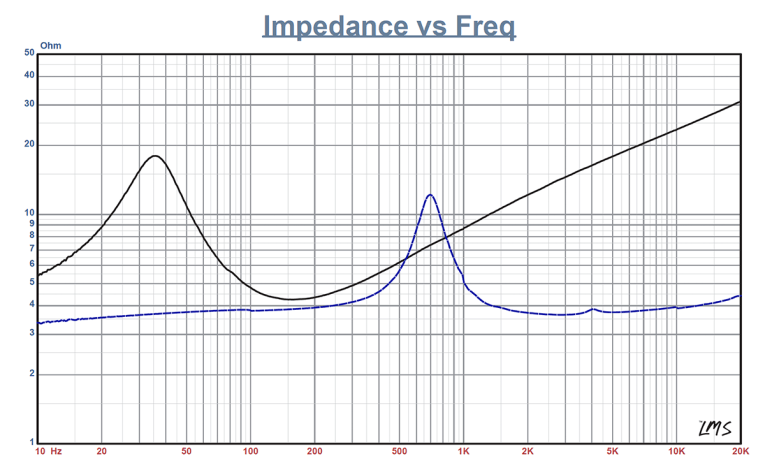
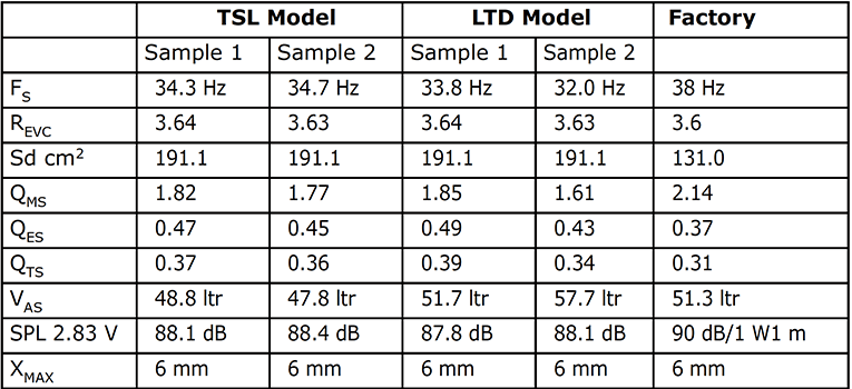
Figure 1 shows the woofer’s 1 V free-air impedance curve (solid black curve) and the tweeter’s impedance curve (dashed blue curve). Table 1 compares the LEAP 5 LTD and TSL data and factory parameters for both W8-2314 samples. Parameter measurement results for the W8-2314 were reasonably close to the factory data except for some minor deviation in the sensitivity due to different criteria (2.83 V vs. 1 W/1 m).
Since everything looked good, I proceeded to set up two computer enclosure simulations using the LEAP LTD parameters for Sample 1. This produced enclosure simulations — a 0.68 ft3 Butterworth (Qtc = 0.7) sealed box alignment with 50% fiberglass fill material, and a 1.13 ft3 QB3 vented box alignment with 15% fiberglass fill material.
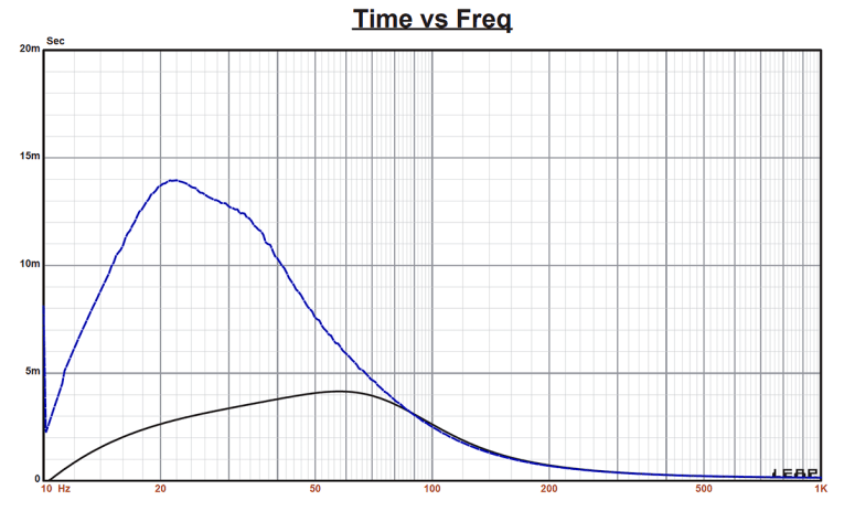
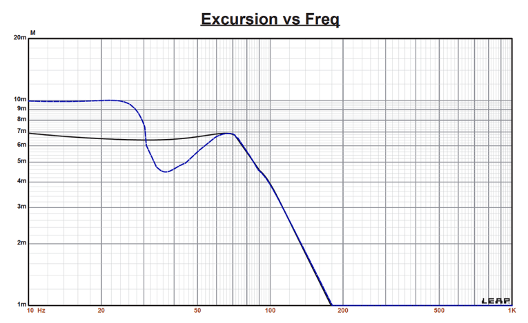
Figure 2 displays the results for the W8-2314 woofer in the sealed and vented simulated enclosures at 2.83 V and at a voltage level sufficiently high enough to increase cone excursion to Xmax + 15% (6.9 mm for the W8-2314). This produced a F3 frequency of 69 Hz (-6 dB = 62 Hz) for the sealed box with a Qtc = 0.77, and a –3 dB = 47 Hz (-6 dB = 39 Hz) for the vented enclosure. Maximum linear excursion (Xmax + 15%) resulted in 109 dB at 23 V for the closed box enclosure simulation and 111 dB at 27 V input for the vented simulation. Figure 3 shows the 2.83 V group delay curves and Figure 4 shows the 23 V/27 V excursion curves.
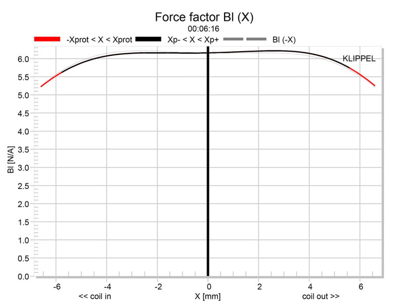


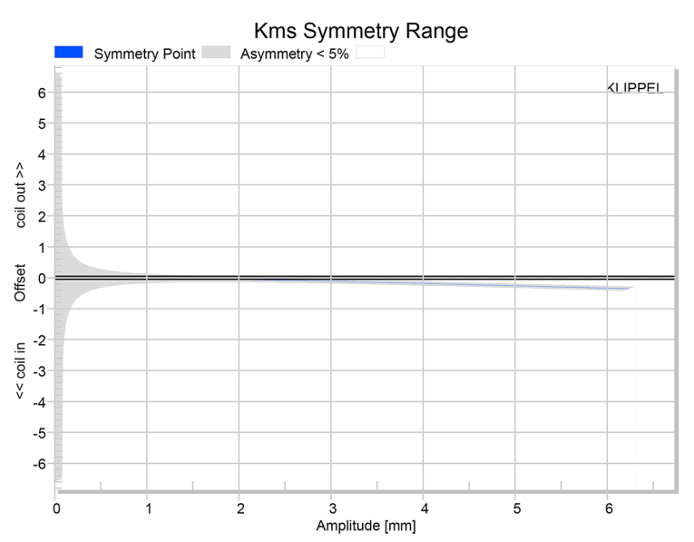
Klippel analysis for the W8-2314 woofer produced the Bl(X), Kms(X) and Bl and Kms symmetry range plots shown in Figures 5-8. The Bl(X) curve for the W8-2314 woofer (Figure 5) is rather broad and symmetrical, with a degree of coil-out offset. Looking at the Bl symmetry plot (Figure 6), the displacement resolves to near zero (0.05 mm) at the 6 mm physical Xmax position. Figure 7 and Figure 8 show the Kms(X) and Kms symmetry range curves for the W-2314 woofer. The Kms(X) curve is also fairly symmetrical in both directions, as well as having relatively amount of coil-in offset. Looking at the Kms symmetry range plot (Figure 8), the offset resolves to 0.28 mm at the physical 6 mm Xmax position.
Displacement limiting numbers calculated by the Klippel analyzer fwere XBl at 82% Bl >5.6 mm and for XC at 75% Cms minimum was 1.9 mm, which means that for this home audio 8” woofer, the compliance is the most limiting factor for the prescribed distortion level of 10%. While the 1.9 mm for XC seems really low, if you look at the multi-voltage impedance curves taken in free-air you can see that as voltage increases, the W8-2314’s resonance climbs rather quickly above 10 V.
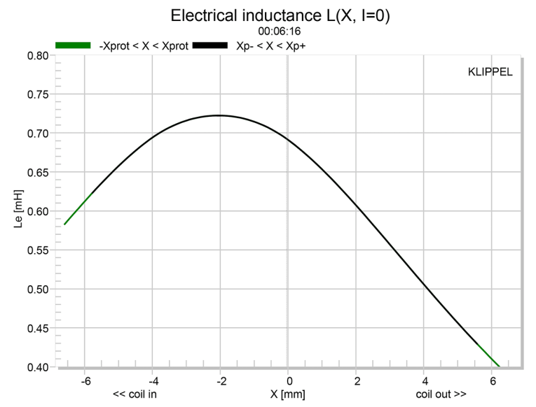
Given the ear’s lack of sensitivity to low-frequency distortion, this driver likely sounds fine at nominal SPL levels, but may suffer at really high SPL above 95 dB to 100 dB. Figure 9 shows the impedance curves. This a really interesting driver, so I don’t think that is a negative, I would just suggest that for higher SPL applications, the driver be high-passed at 100 Hz and incorporated with a 8” to 10” subwoofer. And the last Klippel graph, Figure 10, shows the W8-2314’s inductance curve L(X). The inductance swing from 0 mm to Xmax in and out is a maximum of 0.27 mH, so reasonably controlled.

That said, I proceeded to mount the W8-2314 in an enclosure, which had a 16” × 9” baffle, filled with foam damping material. I then measured both the woofer and the tweeter’s on- and off-axis frequency response from 200 Hz to 40 kHz normalized to 2.83 V/1 m using the Loudsoft FINE R+D analyzer and the GRAS 46BE microphone using the cosine windowed FFT method. All of these SPL measurements also included a 1/12 octave smoothing.
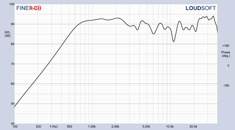
Figure 11 gives the W8-2314 woofer’s on-axis response. Figure 12 shows the tweeter’s on-axis response. The woofer has a smooth rising response out to 2 kHz with no serious anomalies where it begins a typical second-order low-pass roll-off. For the tweeter, the response extends from 800 Hz to 36 kHz.
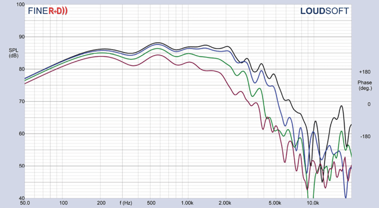
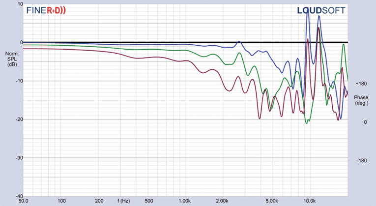
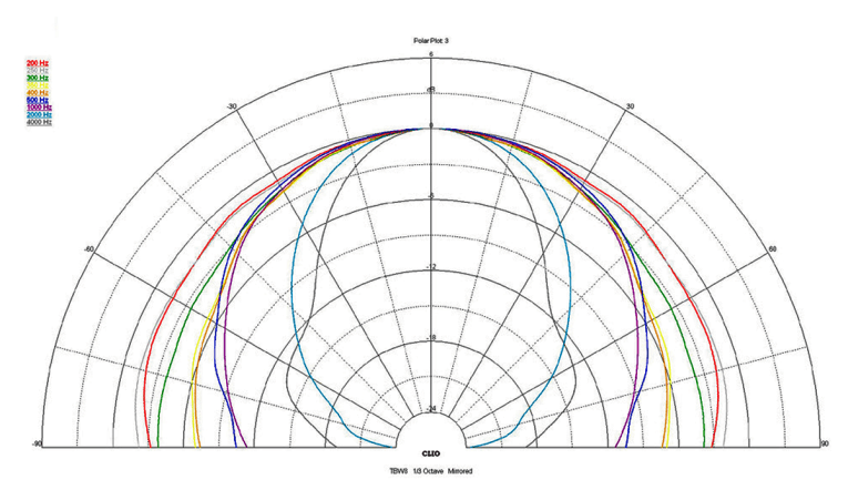
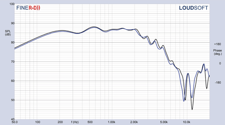

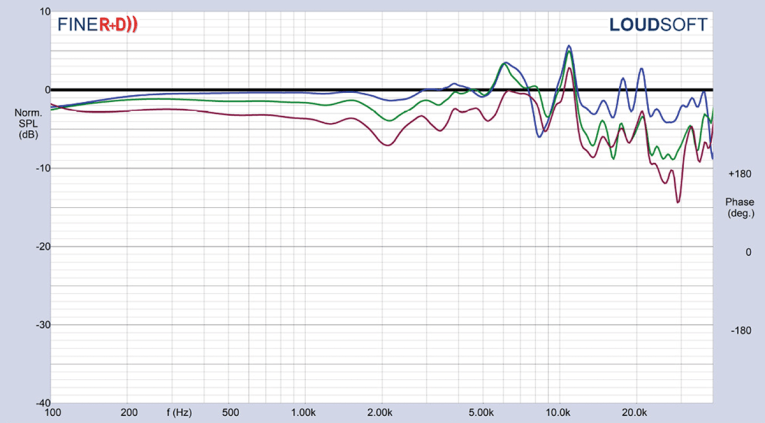
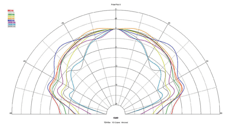
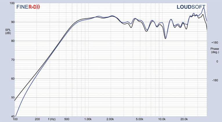
For the tweeter, Figure 17 shows the on- and off-axis horizontal frequency response out to 45°. Figure 18 shows the normalized version. Figure 19 shows the Clio 180° polar plot (processed in 10° increments). Figure 20 depicts the two-sample SPL comparison for the TB Speaker tweeter, which is also within 0.5 dB to 2 dB throughout the entire frequency range.
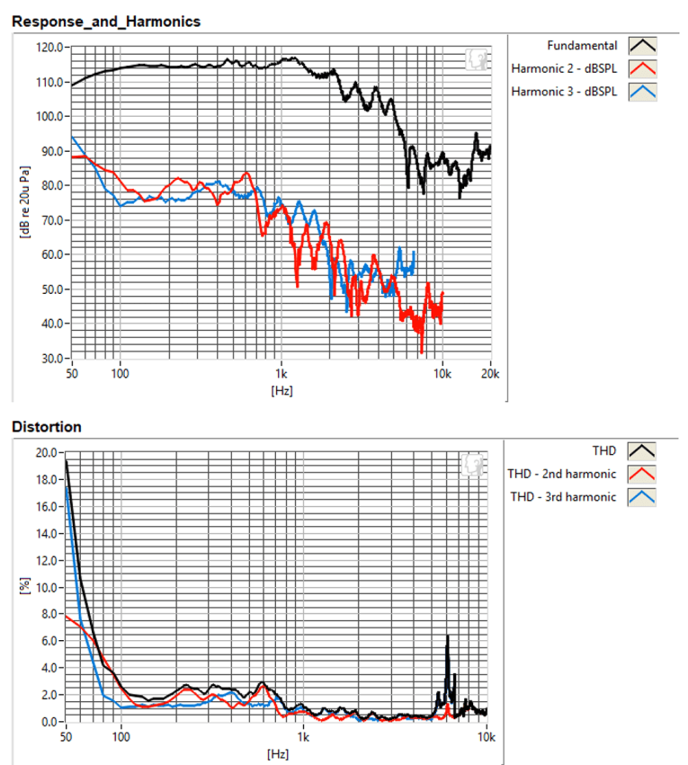



The final group of tests was performed using the Listen, AudioConnect analyzer and SC-1 microphone along with the SoundCheck 17 software to measure distortion and generate time-frequency plots. Setting up for the distortion measurement consisted of mounting the driver rigidly in free-air, and using a pink noise stimulus to determine the voltage level to raise SPL to 94 dB at 1 m. (SoundCheck has a software generator and SPL meter as two of its utilities.)
Next, I measured the distortion with the Listen microphone placed 10 cm from the midrange’s dust cap and the tweeter dome. Figure 21 shows the distortion curves for the woofer (7.86 V). Figure 22 shows the distortion curves for the tweeter dome (3.85 V).
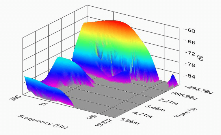
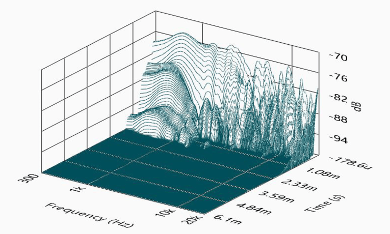
With the distortion tests completed, I next set up SoundCheck 17 to produce a 2.83 V/1 m impulse response for both the W8-2314 woofer and the tweeter and imported the data into Listen’s SoundMap Time/Frequency software. Figure 23 shows the resulting CSD waterfall plot for the W8-2314 woofer. Figure 24 shows the resulting CSD waterfall plot for the tweeter dome. Figure 25 shows the Wigner-Ville logarithmic surface map for the woofer. Figure 26 shows the Short Time Fourier Transform (STFT) graph for the 25 mm aluminum/magnesium tweeter.
I would definitely applaud TB Speaker for its innovation in the development of this coaxial transducer. For more information, visit www.tb-speaker.com. VC
This article was originally published in Voice Coil, July 2019.


