According to Chris Rose, President of Eminence, the new line was developed over the past two years to support the undisputed growth of professional audio. Touring Sound professionals want to move more air, more efficiently without failures in a wide range of applications and venues. Needless to say, the Tour Grade pro sound product group represents a new landmark line from Eminence.
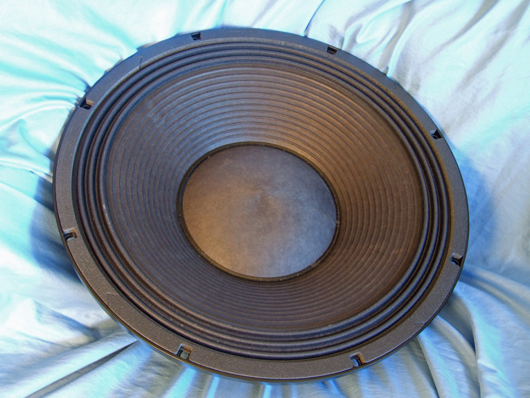
Applications for the new Eminence 48 lb. behemoth NSW6021-6 are primarily as a dedicated subwoofer in bass reflex designs for large venue touring systems. The feature set for the NSW6021-6 is similar to all high-performance pro sound drivers — detailed and substantial.
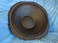
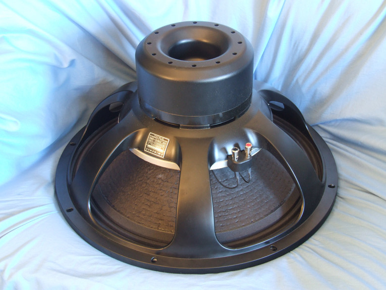
Starting with the frame, the NSW6021-6 uses a proprietary heavy duty six-spoke cast-aluminum frame, incorporating six 50 mm × 8 mm rectangular vent holes in the area below the spider mounting shelf for enhanced voice coil cooling. This category of cooling vents allows air to move past the voice coil and across the front side of the neodymium motor assembly. Additional venting is provided by 12 round 7-mm diameter peripheral vents in the top (back) of the black painted motor return cup. There is also another 38-mm diameter central vent, providing the substantial cooling a 6” diameter 2500 W voice coil requires.
The cone assembly consists of a straight-profile thick “X5” pulp paper ribbed cone along with an 8” diameter convex paper dust cap. Compliance is supplied by pleated coated “advanced” polycotton M-type surround and from two 10” diameter flat cloth spiders (dampers) mounted back-to-back on a 12 mm height aluminum standoff at the base of the frame. The entire cone assembly (cone, surround, and spider) is water-resistant.
Eminence’s NSW6021-6 motor is built around a neodymium ring magnet structure. The neodymium magnet motor was FEA-designed using a 152 mm (6”) diameter voice coil wound with round copper wire on a non-conducting fiberglass former, and incorporates, according to Eminence, a “huge” shorting ring (faraday shield). Motor parts, such as the return cup and the rear heatsink plate that form the spider vents, are coated with a black heat-emissive coating for improved cooling. Factory-rated power handling for this driver is 2,500 W AES, 5,000 W music program, and 10,000 W peak power. Last, the voice coil is terminated to a pair of chrome, color-coded push terminals.


To start testing, I used the LinearX LMS analyzer and VIBox to create both voltage and admittance (current) curves with the driver clamped to a rigid test fixture in free-air at 1 V, 3 V, 6 V, 10 V, 15 V, 20 V, 30 V, and 40 V—allowing the voice coil to progressively heat up between sweeps with a 200 Hz sine wave. Note that the NSW6021-6, like the NSW4018‑8, was still quite linear at 40 V and certainly could have probably be tested at 50 V or greater, but I generally call it quits with high-efficiency pro sound drivers at 30 V to 40 V due to the sound pressure level (SPL) in my parameter test room, and that includes wearing hearing protection!
Following my established protocol for Test Bench testing, I no longer use a single added-mass measurement and instead use the measured Mmd data (469.7 grams for the NSW6021-6). I post-processed the 16 550-point stepped sine wave sweeps for each NSW6021-6 sample and divided the voltage curves by the current curves to generate impedance curves, with the phase derived using the LMS calculation method. I imported the data, along with the accompanying voltage curves, into the LEAP 5 Enclosure Shop software.
Because the Thiele-Small (T-S) parameters provided by the majority of OEM manufacturers is generated using either the standard model or the LinearX LEAP 4 TSL model, I also created a LEAP 4 TSL parameter set using the 1 V free-air curves. I selected the complete data set, the multiple voltage impedance
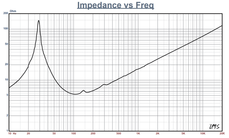
curves for the LTD model, and the single 1 V impedance curve for the TSL model in LEAP 5’s Transducer Model Derivation menu and created the parameters for the computer box simulations. Figure 1 shows the 1 V free-air impedance curve. Table 1 compares the LEAP 5 LTD and TSL data and factory parameters for both of NSW6021-6 samples. LEAP 5 parameter calculation results for the NSW6021-6 correlated well with the Eminence factory datasheet.
Note that since the LTD measurements are multi-voltage, designed to produce better high voltage excursion curve simulations, I am really only comparing factory TSP to the TSL parameters, which look good. Also the published coil length and gap height dictate a 14.63 mm Xmax, so the quoted 21 mm factory Xmax is specifically accounting for the gap area fringe field, which is essentially what I am doing using Xmax +15% for maximum SPL calculations.
Following my established measurement protocol, I configured computer enclosure simulations using the LEAP LTD parameters for Sample 1. Eminence has a set of four specific box volumes and tunings for the NSW6021-6 that are broken down into a small, medium, large, and dual driver categories, so I decided to use the small and large volumes for this enclosure simulations. Given that I set up two computer box simulations in LEAP 5—the first a vented box with a 6.6 ft3 volume (15% fill material) tuned to 38 Hz; and a larger vented alignment with a 13.1 ft3 volume tuned to 25 Hz, also simulated with 15% fiberglass damping material.
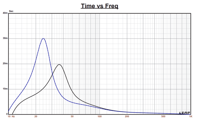
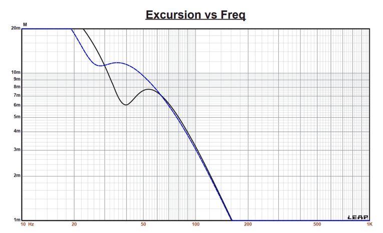
Figure 2 displays the results in the two vented enclosures at 2.83 V and at a voltage level sufficiently high enough to increase cone excursion to Xmax + 15% (16.8 mm for the NSW6021-6). This produced a F3 frequency of 36 Hz (F6 = 32.4 Hz) for the 6.6 ft3 vented alignment and -3 dB = 24 Hz (F6 = 21 Hz) for the 13.1 ft3 vented simulation. Increasing the voltage input to the simulations until the maximum linear cone excursion was reached resulted in 128 dB at 100 V for the 6.6 ft3 box and 121 dB for the same 100 V input level for the larger 13.1 ft3 vented box. Figure 3 shows the 2.83 V group delay curves. Figure 4 shows the 100 V excursion curves.
Please note that the drivers were not excursing beyond 16.8 mm at 100 V so I would conclude that the NSW6021-6 is more thermally limited than excursion limited, which is a good thing. Even still, incorporating a 20 Hz fourth-order high-pass filter would prevent over excursion of very low frequency information and subsonic noise.
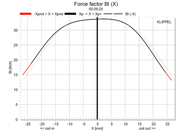
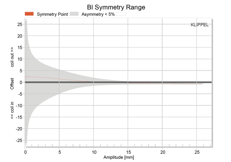
Klippel analysis for the NSW6021-6 would normally be provided using our DA2 Klippel analyzer (provided courtesy of Klippel GmbH), and performed by Pat Turnmire, of Redrock Acoustics. However, Turnmire was unavailable, and since Eminence has its own DA2, they graciously provided me with the KBDX files for the NSW6021-6, which is what I used to produce the Bl(X), Kms(X), and Bl and Kms symmetry range plots given in Figures 5-8.
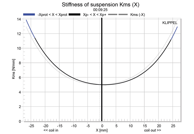
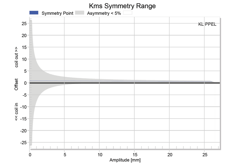
The Bl(X) curve for the NSW6021-6 (see Figure 5) is very broad and symmetrical with some small amount of tilt and offset. Looking at the Bl symmetry plot (see Figure 6), this curve shows a very small 0.32 mm coil-in offset at the physical Xmax (14.3 mm), so a very nice Bl profile. Figure 7 and Figure 8 show the Kms(X) and Kms symmetry range curves for the NSW6021-6. The Kms(X) curve is also mostly symmetrical in both directions accompanied by an amount of coil-out offset. Looking at the Kms symmetry range plot, the coil-out offset at the physical Xmax excursion point of the driver is an also inconsequential 0.13 mm. Displacement limiting numbers calculated by the Klippel analyzer for the NSW6021-6 were XBl at 70% Bl = 18.8 mm and for XC at 50% Cms was 21.4 mm — which means that for this driver, the Bl was the most limiting factor for the 20% distortion level. However, both numbers were considerably beyond the physical Xmax of this driver. At the risk of repeating myself after discussing the 18” Tour Grade woofer last month, this driver has “excursion for days.”
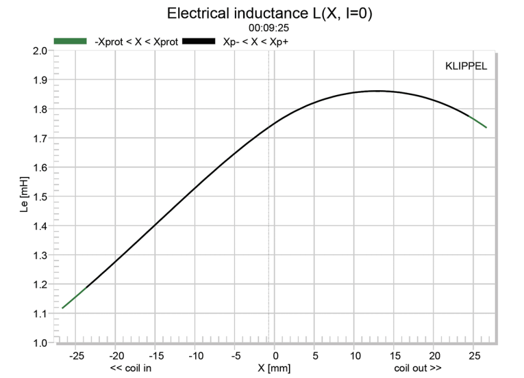
Figure 9 gives the inductance curves Le(X) for the NSW6021-6. Inductance will typically increase in the rear direction from the zero rest position as the voice coil covers more pole area, which is not what is happening here mostly due to the shorting ring. The inductance swing for this driver is 0.34 mH coil-in Xmax to 0 and 0.11 mH coil-out from 0 to Xmax, which for a 6” diameter voice coil driver is very, very low.
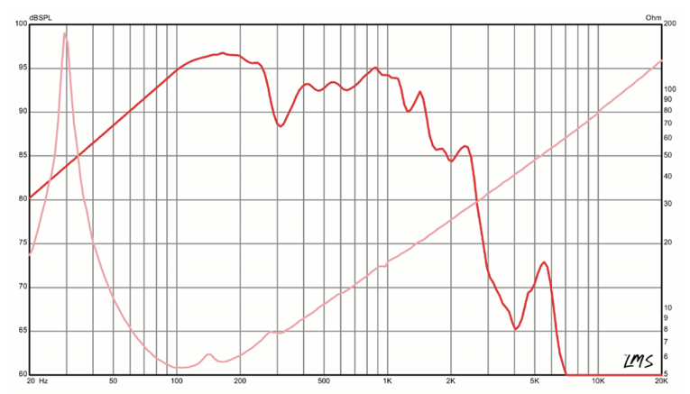
Since I do not have the logistic capability of performing frequency response measurements on- and off-axis with 21" diameter woofers and also because 21" drivers are generally crossed over below 500 Hz where there generally isn’t much that is relevant in terms of frequency variation, I have just included the factory on-axis frequency response (see Figure 10).
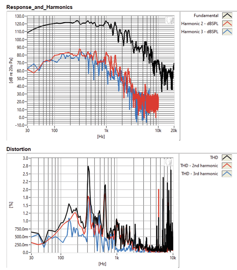
For the last test executed on the NSW6021-6, I employed the Listen, Inc. SoundCheck software and AudioConnect analyzer along with SCM 1/4” microphone to measure distortion (courtesy of my friends at Listen, Inc.). I would normally also do time domain testing, but again, since I don’t keep an inventory of 18” to 21” text boxes for this purpose, these tests were not conducted. For the distortion measurement, I mounted the 21” driver rigidly in free-air, and set the SPL to 104 dB at 1 m (12.5 V) using a pink noise stimulus. Then, I measured the distortion with the Listen microphone placed 10 cm from the driver. This produced the distortion curves shown in Figure 11. Please note that the voltage level depends a lot on the spectral content of the driver, not so much on the sensitivity.
Eminence is one of the older names (founded in 1966) in the pro sound industry and has a justifiably highly regarded reputation. The data presented for the NSW6021-6 certainly speaks to that fact. For more information about this NSW6021-6 woofer and other Eminence pro sound and musical instrument drivers, visit www.eminence.com. VC
This article was originally published in Voice Coil, June 2020.