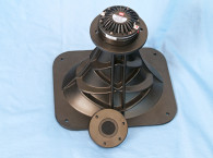
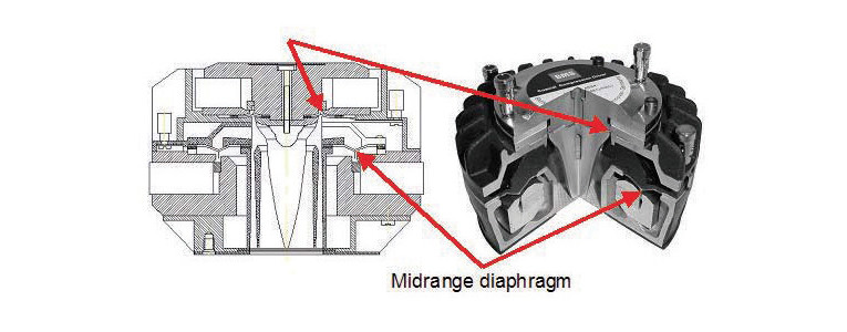
Figure 1 shows a cutaway view of the BMS 4592 coaxial compression driver, which has an internal construction similar to that of the BMS 4507ND. The driver’s body contains two separate subsystems with each one driven by a separate motor structure, magnet, and voice coil. The midrange diaphragm feeds in from around the phase plug’s peripheral. The tweeter diaphragm is located at the phase plug’s base. This is similar to the concept JBL used in its D2 compression driver for the VTX series. However, JBL combined two separate voice coils and diaphragms mixed in parallel together. BMS uses a two-way midrange/tweeter design with two voice coils and diaphragms. BMS also introduced its 4599ND dual-diaphragm compression driver that incorporates two identical 3.5” concentric annular ring diaphragms connected to a common 2” throat. The design results in extremely high acoustical output with two large annular diaphragms covering 200-to-9,000-Hz frequency range, which is similar to the JBL D2 concept.
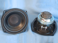
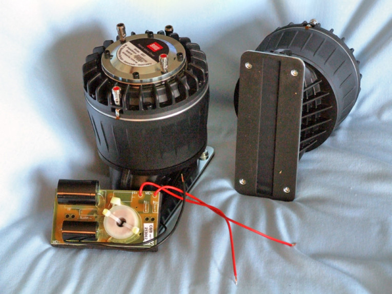
The 4507ND’s features include a 300-Hz to 22-kHz bandwidth (6 to 22 kHz for the tweeter and 400 Hz to 6.3 kHz for the midrange), Kapton voice coil formers wound with copper-clad aluminum wire (two layers on the inside of the former and two layers on the outside), a 1.75” (44.4-mm) voice coil diameter for the tweeter, a 3.5” (90-mm) voice coil diameter for the midrange, two neodymium ring magnets, polyester diaphragms, 1,000-W peak midrange power handling above 500 Hz, and a 320-W peak for the high-frequency driver, plus color-coded chrome push terminals for each coaxial section (see Photo 1).
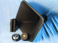
The rectangular planar waveguide measures 6.5” × 0.75” (162 mm × 19 mm) and is optimized for 0° to 15° vertical dispersion and up to 120° in the horizontal plane. Since the midrange and tweeter are coincident, the planar wave driver enables excellent acoustic phase coherent coupling for a smooth line source effect.
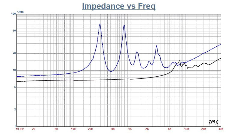
I decided to simultaneously present the test data for the BMS 4507ND planar midrange and the tweeter. I began with 200-point LMS impedance sweeps for both the midrange and the tweeter including the waveguide. Figure 2 shows the midrange and the tweeter impedance curves with waveguide in place (unlike regular compression drivers, these will never be used with different horns). Minimum impedance for the midrange is 9.6 Ω at 459 Hz with an 8.58-Ω direct current resistance (DCR). For the tweeter, minimum impedance in its operating range is 10.9Ω at 10.3 kHz with a 6.98-Ω DCR.
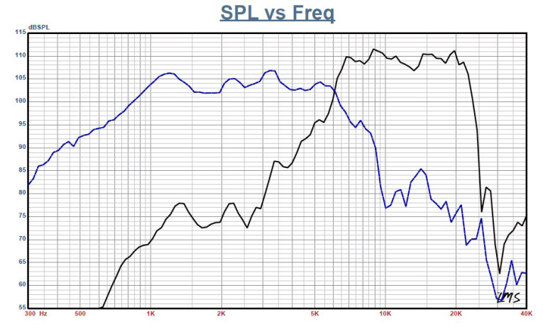
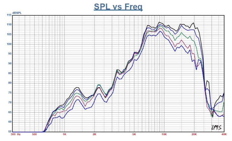
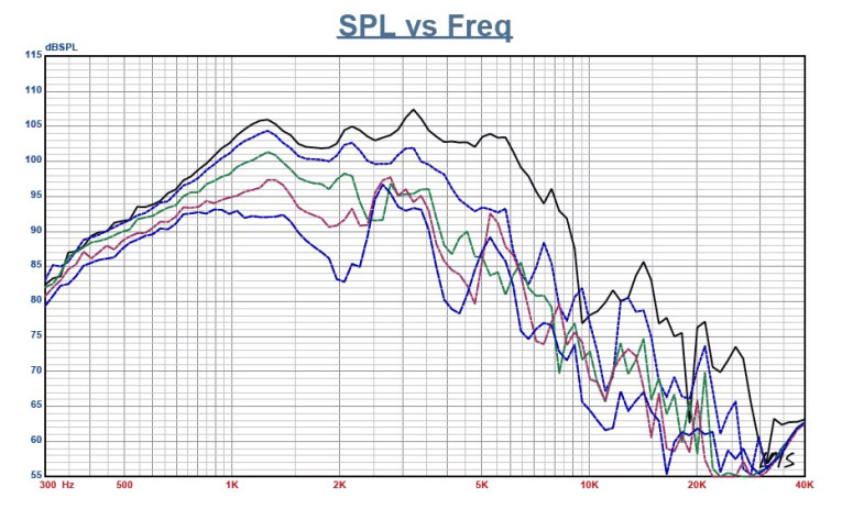
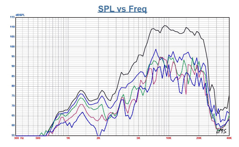
Next, I mounted the driver combination in an enclosure with a 6” (width) × 9” (height) baffle dimension and produced on- and off-axis frequency response curves out to 60° off from 300 Hz to 40 kHz. Figure 3 shows the tweeter and midrange on-axis response with the overlapping range for each section of the 4507ND. Next, I measured each section of the 4507ND from 0° to 60° in the horizontal and vertical planes from 300 Hz to 40 kHz. Figure 4 shows the midrange’s horizontal response. Figure 5 shows the tweeter’s horizontal response. Figure 6 shows the midrange’s vertical response.
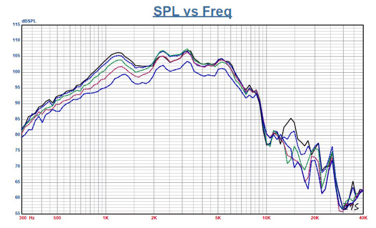
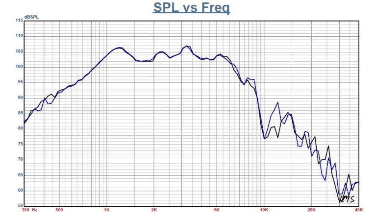
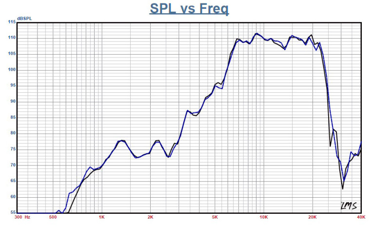
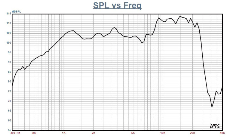
Figure 7 shows the tweeter’s vertical response. The final sound pressure level (SPL) measurements compare the two coaxial sections of Sample A with Sample B, illustrated for the midrange and tweeter in Figure 8 and Figure 9, respectively. Both sections had a close match within 0.5 dB of the driver’s operating range.
The 4507ND could also be biamped using an electronic crossover (e.g., a miniDSP balanced 2 × 4 crossover/equalizer with the phase zeroed out). A BMS passive network would also work. Figure 10 shows the on-axis summation of the midrange and high-range sections using the BMS passive crossover. This network uses a first-order low-pass filter for the midrange and a second-order high-pass for the tweeter.
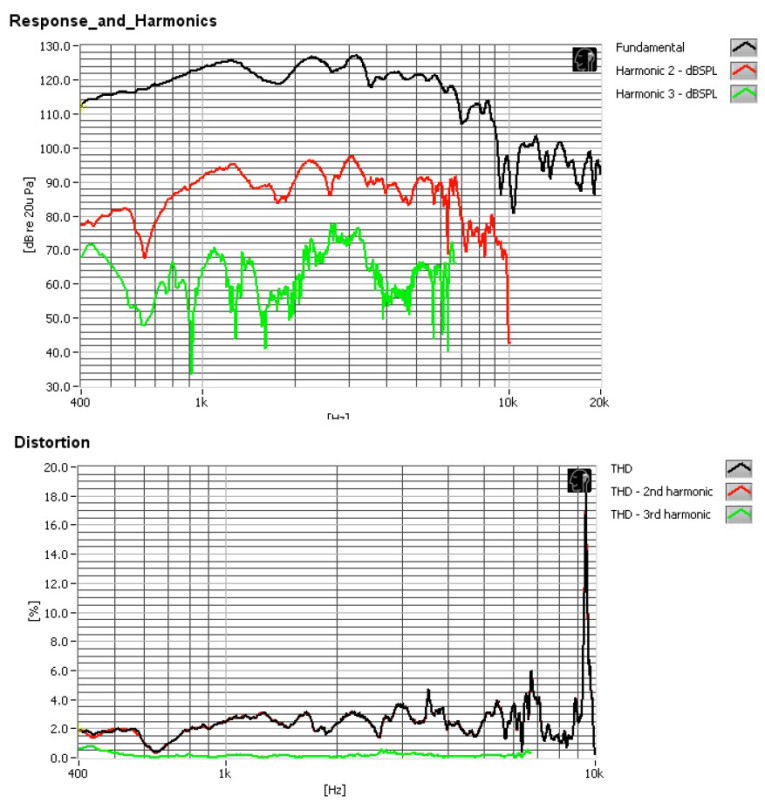
However, it does not incorporate any resistance padding for the tweeter, but it could easily be added. Next, I set up the Listen SoundCheck AmpConnect analyzer and the SCM 0.25” microphone to produce distortion and time decay plots. For the distortion plots, I set the SPL of both sections of the 4507ND combination to 104 dB at 1 m, which took 2.1 V for the tweeter and 3.8 V for the midrange. I placed the microphone 10 cm from the horn’s mouth. Figure 11 shows the midrange’s two distortion plots (measured from 500 Hz).
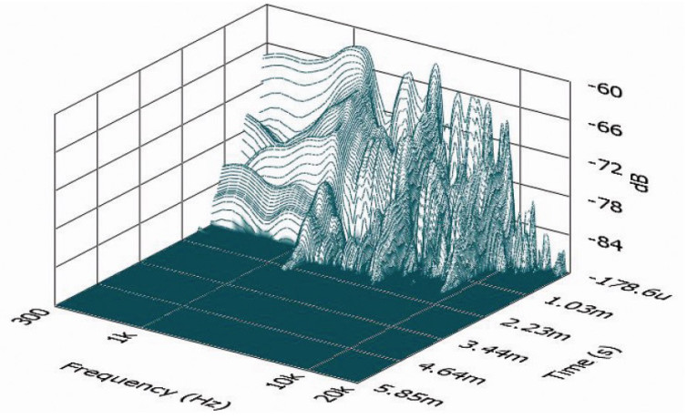
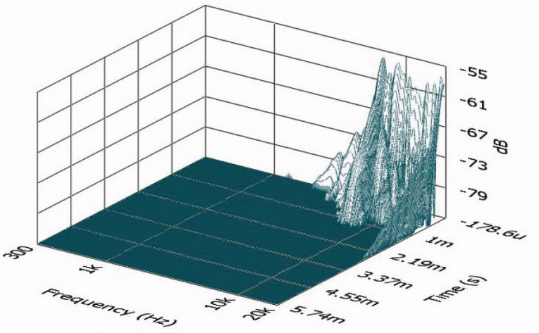
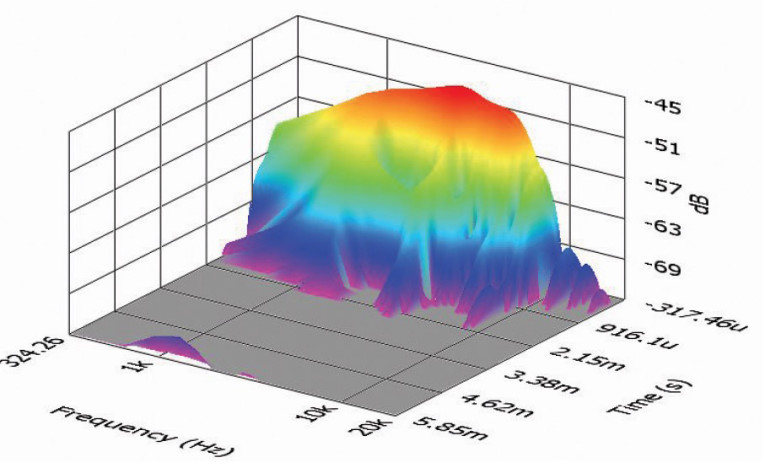
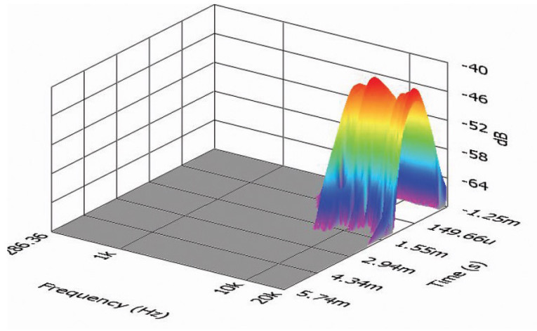
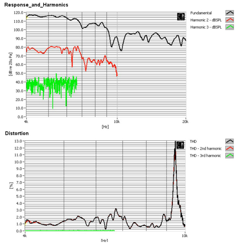
Figure 12 shows the tweeter’s two distortion plots (measured from 4 kHz). Next, I created impulse response curves for the midrange and tweeter at 2.83 V/1 m and loaded the data into the Listen SoundMap software to produce the cumulative spectral decay (CSD) waterfall plots and the short-time Fourier Transform (STFT) plots. Figure 13 and Figure 14 show the waterfall plots for the midrange and the tweeter, respectively.
Figure 15 and Figure 16 display the STFT plots for the midrange and the tweeter, respectively. BMS Speakers’s patented dual-diaphragm technology is seriously impressive as is the 4507ND planar wave driver’s performance and build quality. For more information, visit www.bmsspeakers.com VC
This article was originally published in Voice Coil, May 2014.