While B&C Speakers made a significant number of improvements in the new DCX354-16, it is still basically a smaller version of the DCX464. The DCX464 has 4” diameter midrange diaphragm and a 2.5” high-frequency diaphragm, while the DCX354 has a 3” midrange diaphragm and a 2” high-frequency diaphragm, such that the DCX464 was good down to 300Hz, and the DCX354-16 down to 400Hz on the low end.
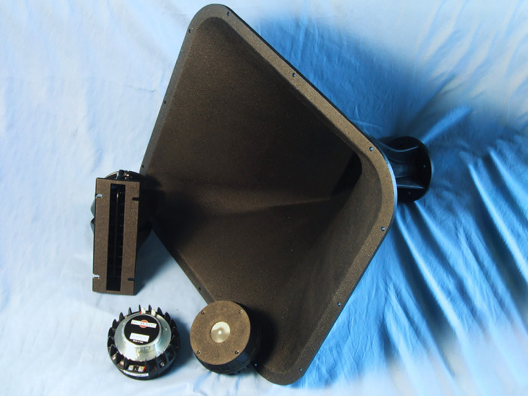
The horn that I tested with the DCX354-16 was the new B&C Speakers ME464. This is a very large horn device made of durable polyurethane plastic, and is I think the largest pro sound horn available. In terms of size, it has a depth of 18” and a front mouth that measures 22.6” wide and 19.9” tall. It’s a 1.4” entrance constant directivity horn with an 80° × 60° nominal coverage pattern, and loads well down to 300Hz. This would be perfect for use in a midrange tweeter midrange (MTM) array with two 15” or 18” woofers.
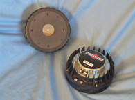
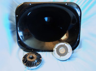
Looking at Photo 1 and Photo 2, you will also notice another B&C Speakers device that is compatible with the DCX364 (or any other 1.4” exit driver), the ME148 line array optimized waveguide with a horizontal dispersion of 120° and response down to 500Hz (you can read more about this device on the B&C Speakers website).
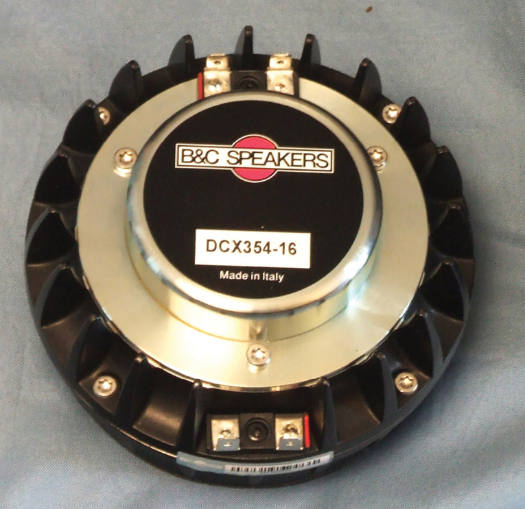
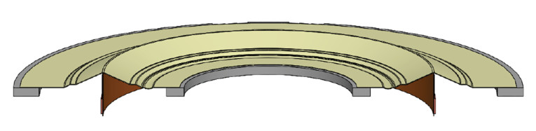
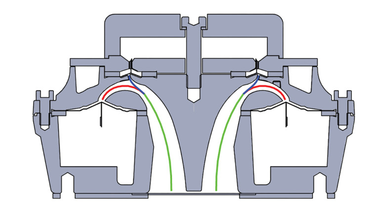
It terms of features, the DCX354-16 ring radiator is listed as a 1.4” (36mm) throat compression driver, and that is for both the midrange driver and the high-frequency driver (see the diaphragm drawing in Figure 1), which means that B&C Speakers has found a way to mix both drivers in the same throat. This is done with a patented midrange integrator that allows both diaphragms to work together over a wide frequency range without causing any major magnitude or phase errors, as seen in the motor cutaway diagram in Figure 2.
The midrange compression driver has a 16Ω nominal impedance, continuous power handling of 180W, 112.7dB (1W/1m) sensitivity, and a frequency range of 400Hz to 6kHz. Other features include a neodymium ring magnet motor structure, high-temperature polymer diaphragm (PEEK), 76mm (3”) diameter voice coil wound with aluminum wire on a non-conducting former, and a recommended high-pass crossover frequency of 400Hz.
Nominal impedance for the high-frequency section is also 16Ω, and has a 160W continuous power handling rating. The voice coil diameter is 51mm (2.0”), also wound with aluminum wire on a non-conducting former and powered by a neodymium slug. It likewise utilizes a high temp polymer diaphragm (PEEK), which resulted in a somewhat higher sensitivity of 114.6dB (1W/1m with an applied RMS voltage of 4V). The recommended high-pass crossover frequency DCX354-16 high-frequency device is 4.5kHz to 5kHz.
Testing the B&C Speakers DC354/ME464 horn began using the LinearX LMS analyzer to produce the 300-point stepped sine wave impedance plot for midrange section, which is shown in Figure 3. The solid black curve represents the DCX354-16 midrange mounted on the horn and the dashed blue curve represents the midrange compression driver without the horn. With a 8.95Ω DCR (Re), the minimum impedance of the midrange/ME464 horn section of the DCX354 was 11.6Ω and at 4.6kHz.
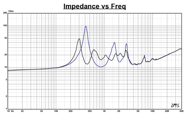
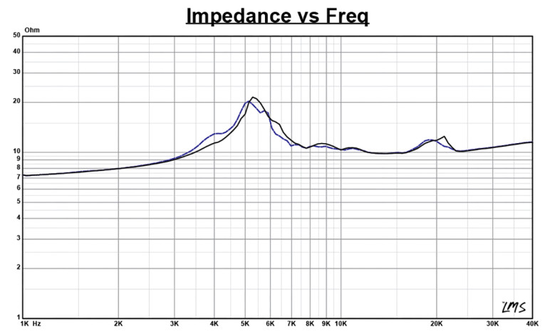
Figure 4 gives the same impedance data for the high-frequency section, with the solid black curve representing the DCX354-16 high-frequency driver mounted on the horn and the dashed blue curve representing the high-frequency compression driver without the horn. It’s obvious that horn loading has very little effect in this frequency range. With an 8.96Ω DCR (Re), the minimum impedance of the high frequency/ME464 horn section of the DCX354-16 was 9.84Ω at 13.94kHz.
For the next set of SPL measurements, I free-air mounted the DCX354/ME464 horn combination without an enclosure and measured just the horizontal on- and off-axis at 2.83V/1m of the midrange and high-frequency section, again using the Loudsoft FINE R+D analyzer (provided to Voice Coil by Loudsoft) and the GRAS 46BE ¼” microphone (courtesy of GRAS Sound & Vibration). The analyzer was set up to measure the 200Hz to 40kHz frequency response (using a 192kHz sampling rate) at 2V/0.5m normalized to 2.83V/1m. Sweeps were performed at 0°, 15°, 30°, 45°, and 60°.
I only measured the horizontal measurements out to 60° and did not take vertical measurements or the normal CLIO polar plot measurements, primarily because my horn test fixture is not quite robust enough to do a lot of manipulation with such a seriously large horn. In terms of the horn’s directivity, the ME464 horizontal and vertical polar plots are provided in Figure 5 and Figure 6, respectively (the horizontal and vertical spectral directivity maps can be seen on the B&C Speakers website).

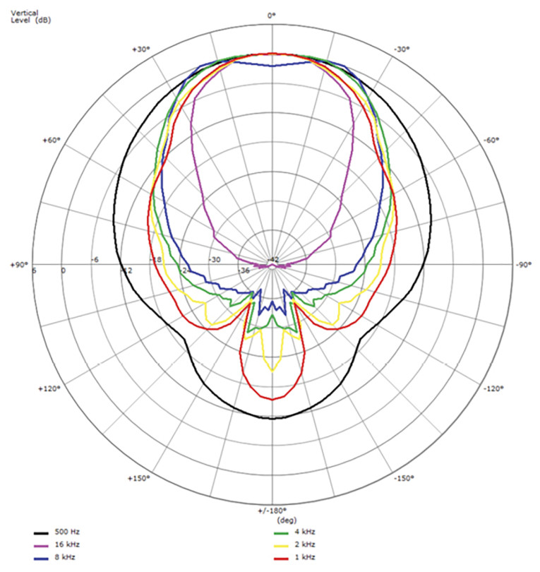
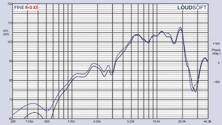
Figure 7 illustrates the on-axis frequency response of both the midrange and high-frequency compression driver/horn combinations. This midrange measurement was done by splicing (the FINE R+D software splice routing is excellent and simple to operate) a “close” field measurement with the GRAS microphone located flush with the horn opening and windowed at 200ms to an on-axis response windowed to 6.2ms to produce a more accurate low-frequency response for the midrange.
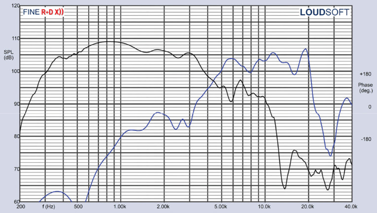
As can be seen, the midrange of the DCX354-16 compression driver mounted in the ME464 horn has output down to about 350Hz. Overall, the midrange response is a smooth ±2.5dB, exhibiting no major anomalies in its operating range to the low-pass roll-off that begins at about 3kHz. The high-frequency section is about ±2.5dB to 3dB throughout its operating range out to 20kHz.
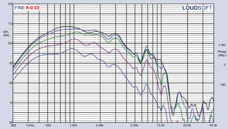
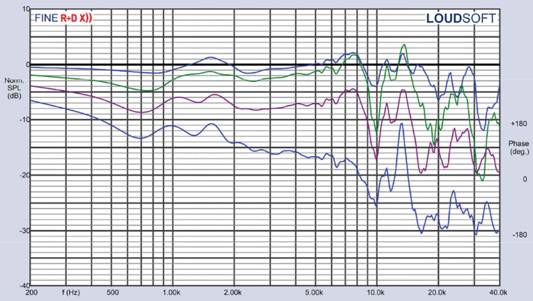
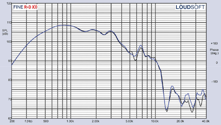
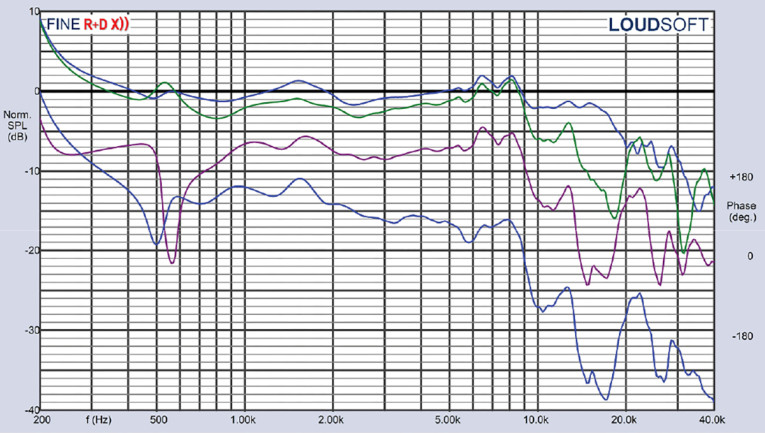
Figure 8 depicts the midrange on- and off-axis (0° to 60°) response in the horizontal plane. Figure 9 displays the normalized version of Figure 8. Figure 10 illustrates the two-sample SPL comparison showing the two B&C Speakers DCX354 midrange sections’ compression drivers matched to less than 1dB throughout the operating range of the midrange transducer.
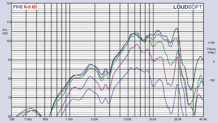
For the high-frequency section, Figure 11 illustrates the on- and off-axis 0° to 60° frequency response, with the normalized version of Figure 11 given in Figure 12. Figure 13 compares both samples of the high-frequency section, with both samples matched to less than 1dB except for a small area centered on 13.5kHz where the deviation was between 1dB to 2dB.
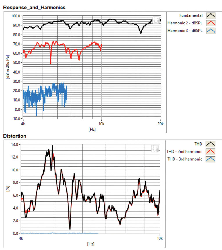
For the remaining series of tests, I set up the Listen AudioConnect analyzer, the SoundCheck 20 software, and the Listen ¼” SCM microphone (courtesy of Listen, Inc.) to measure distortion and generate time-frequency plots. For the distortion measurements, the coaxial DCX354-16/ME464 horn combination was again mounted in free-air in the same manner as was used for the frequency response measurements, and the SPL was set to 104dB at 1m for both the midrange and high-frequency sections (2.04V for the midrange section and 2.33V for the high-frequency section both determined by using a pink noise stimulus generator and internal SLM in the SoundCheck 20 software).
Then, the distortion was measured with the Listen 1/4” measurement microphone located 10cm from the mouth of the horn. This produced the distortion curves shown in Figure 14 (red curve=second harmonic, blue curve= third harmonic) for the DCX354-16 midrange. Figure 15 shows the high-frequency component. Both mid and high sections exhibited very low third-harmonic distortion.

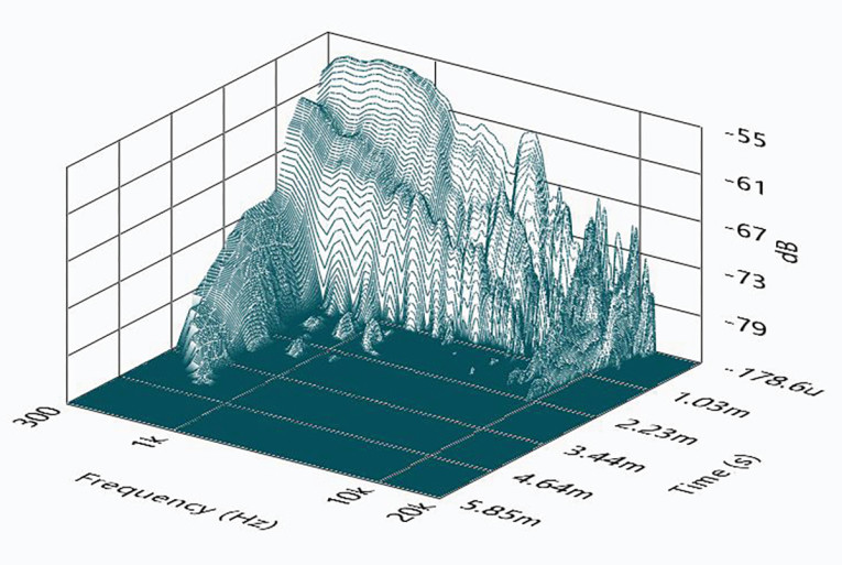
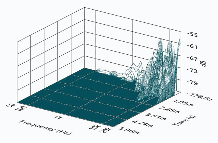
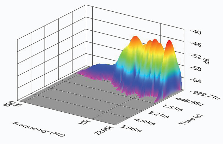
Following the distortion test sequence, I then set up SoundCheck 20 to generate a 2.83V/1m impulse response for both the midrange and high-frequency sections of the driver/horn combination and imported the data into Listen’s SoundMap Time/Frequency software. The resulting cumulative spectral decay (CSD) waterfall plots are given in Figure 16 for the midrange and Figure 17 for the high-frequency driver. The Short Time Fourier Transform (STFT) plot for the midrange section is shown in Figure 18, and Figure 19 shows the STFT plot for the high-frequency driver.

From the above measurements, the new more compact B&C Speakers DCX354-16 1.4” coaxial compression driver displays excellent performance in a high power handling package, and given its wide frequency range from 400Hz to 20kHz in a single horn device, gives PA OEMs an outstanding new transducer with which to work. For more information about this and other pro sound products from B&C Speakers, visit www.bcspeakers.com. VC
This article was originally published in Voice Coil, May 2023